
Additive manufacturing smelting furnace

An additive manufacturing and smelting furnace technology, applied in the field of additive manufacturing, can solve the problems of waste of granular powder and excessive flue gas, and achieve the effects of speeding up smelting, improving stirring and mixing, and facilitating scraping

Pending Publication Date: 2021-11-30
刘敏
View PDF0 Cites 0 Cited by
  • Summary
  • Abstract
  • Description
  • Claims
  • Application Information

AI Technical Summary

Problems solved by technology

[0004] Aiming at the deficiencies of the prior art, the present invention provides a smelting furnace for additive manufacturing, which solves the problem that more flue gas will be generated during smelting, and a part of the particle powder will be wasted due to direct discharge.

Method used


Image

  • Additive manufacturing smelting furnace
  • Additive manufacturing smelting furnace
  • Additive manufacturing smelting furnace

Examples


Embodiment example 1

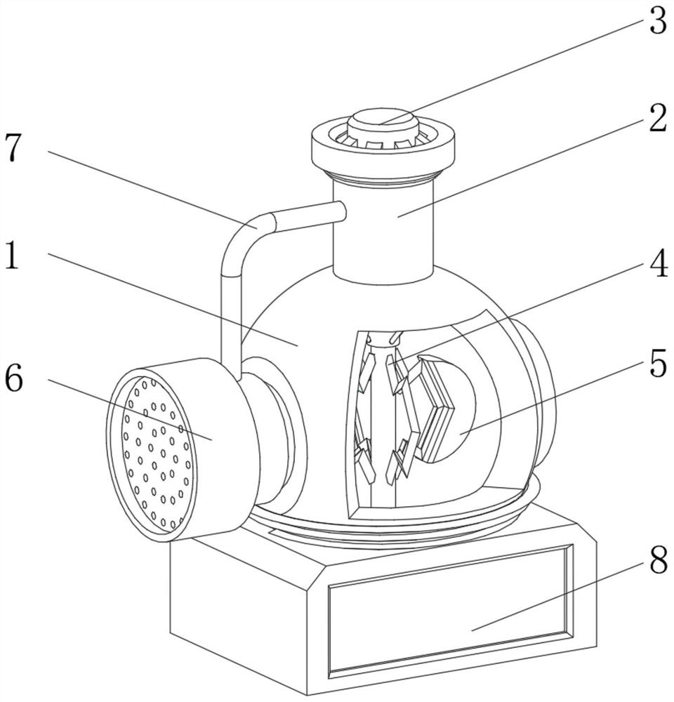
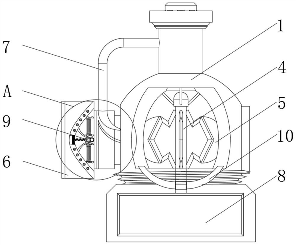
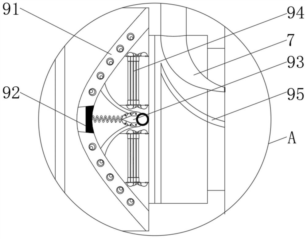
[0033] see Figure 1-3 , the present invention provides a technical solution: a smelting furnace for additive manufacturing, specifically comprising:

[0034] A smelting furnace 1, the smelting furnace 1 has a melting furnace body, and a smelting furnace body tube 2 arranged on the top, and a top exhaust head 3 is arranged on the top of the smelting furnace 1;

[0035] Smelting gas injection head 6, the smelting gas injection head 6 has a gas injection head body, and a gas return pipe 7 arranged above the smelting gas injection head 6, the upper and lower ends of the gas return pipe 7 communicate with the top smelting furnace body pipe 2 respectively;

[0036] A melting furnace base 8, the melting furnace base 8 has a base body, and a melting furnace installation seat arranged above the melting furnace base 8, and a driving mechanism is arranged inside the melting furnace base 8, and the melting furnace 1 also includes:

[0037] An inner smelting rotator 4, the inner smelting...

Embodiment example 2

[0042] On the basis of implementation case 1, please refer to Figure 1-6 , the present invention provides a technical solution: the side device 5 includes a fan-shaped frame 51, an arc-shaped scraper 52 is arranged on the outside of the fan-shaped frame 51, and an elastic telescopic rod 53 is arranged between the arc-shaped scraper 52 and the fan-shaped frame 51. A connection spring 54 is provided between the scraper 52 and the inner side of the sector frame 51 .

[0043] Both sides of the arc-shaped scraper 52 are provided with heating rollers 56, both sides of the arc-shaped scraper 52 are provided with horn contact pieces, both sides of the fan-shaped frame 51 are provided with electrical terminals 55, and the horn contact plates and electrical terminals 55 corresponds to the setting.

[0044]The heating roller part 56 includes a heating column, and a heating ball is installed on the top of the heating column. The heating roller part 56 is electrically connected with the ...


PUM


Abstract

The invention discloses an additive manufacturing smelting furnace. The additive manufacturing smelting furnace specifically comprises a smelting furnace and a smelting gas injection head; the smelting furnace is provided with a smelting furnace body and a top smelting furnace body pipe, a top exhaust head is arranged at the top of the smelting furnace, and a flue gas treatment device is arranged in the top exhaust head; the smelting gas injection head is provided with a gas injection head body and a gas return pipe arranged above the smelting gas injection head, and the upper end and the lower end of the gas return pipe communicate with the top smelting furnace body pipe. The invention relates to the technical field of additive manufacturing. According to the additive manufacturing smelting furnace, the problems that much flue gas is generated during smelting, and part of particle powder is wasted due to direct emission are solved, stirring and mixing of internal smelted materials are improved, the smelting efficiency of the internal materials is improved, the internal pressure is increased, smelting of the internal materials can be accelerated, and the internal materials are prevented from adhering to the inner wall of the smelting furnace during smelting.

Description

technical field [0001] The invention relates to the technical field of additive manufacturing, in particular to an additive manufacturing melting furnace. Background technique [0002] Additive manufacturing, commonly known as 3D printing, is a combination of computer-aided design, material processing and forming technology, based on digital model files, through software and numerical control system, special metal materials, non-metal materials and medical biological materials, according to extrusion, Sintering, melting, light curing, spraying, etc. are accumulated layer by layer to create a manufacturing technology for physical objects. In additive manufacturing, a melting furnace is usually required to melt metal raw materials to provide printing materials for additive manufacturing. Traditional smelting furnaces have fuel heating and electric heating. For fuel-heating smelting furnaces, since more smoke is generated during smelting, direct discharge will cause a part of ...

Claims


Application Information

Patent Timeline
IPC IPC(8): F27D11/00F27D21/00F27D25/00F27D27/00B33Y40/00
Inventor 刘敏
Owner 刘敏
Learn More