Cutting machining equipment for crystalline silicon cells of solar cell panel assembly

A technology for solar panels and crystalline silicon cells, which is used in stone processing equipment, electrical components, sustainable manufacturing/processing, etc. The lack of stability of the cells can achieve the effect of enhancing the cutting effect, reducing safety hazards and reducing processing costs.

Inactive Publication Date: 2021-12-03
江苏晟大光电科技有限公司
View PDF7 Cites 0 Cited by
  • Summary
  • Abstract
  • Description
  • Claims
  • Application Information

AI Technical Summary

Problems solved by technology

[0003] Most of the current crystalline silicon cells are cut and processed by laser cutting, and there are the following problems when using laser cutting equipment to cut and process crystalline silicon cells: 1. Since laser cutting uses high-energy laser beams to irradiate the surface of the workpiece , so that the irradiated area on the crystalline silicon cell is partially melted and gasified, so it is easy to cause thermal melting on the incision of the crystalline silicon cell, thereby affecting the cutting effect of the crystalline silicon cell, and adjusting the cutting of the crystalline silicon cell When the width is wide, the program needs to be re-entered, the operation is cumbersome, and the cost is high
[0004] 2. When the laser cutting equipment cuts the crystalline silicon cell, it cannot limit the position of the crystalline silicon cell, so the crystalline silicon cell lacks stability and cannot ensure the cutting accuracy of the crystalline silicon cell. Crystalline silicon cells are placed on laser cutting equipment, which poses a safety hazard

Method used


Image

  • Cutting machining equipment for crystalline silicon cells of solar cell panel assembly
  • Cutting machining equipment for crystalline silicon cells of solar cell panel assembly
  • Cutting machining equipment for crystalline silicon cells of solar cell panel assembly

Examples


Embodiment Construction

[0032] The embodiments of the present invention will be described in detail below with reference to the accompanying drawings, but the present invention can be implemented in many different ways defined and covered by the claims.

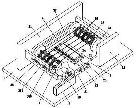
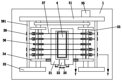
[0033] refer to figure 1 and figure 2 , a solar cell panel assembly crystalline silicon cell cutting and processing equipment, including a base 1, an installation unit 2 and a cutting unit 3, the installation unit 2 is arranged in the middle of the upper end of the base 1, and the cutting unit 3 is installed on the upper end of the base 1 and located in the installation unit 2 outside.

[0034] refer to figure 1 , figure 2 and Figure 6 , the installation unit 2 includes a fixed seat 21, a sliding block 22, a fixed plate 23, a rectangular frame 24 and a fixed assembly 25, wherein: the fixed seat 21 is arranged in the middle of the upper end of the base 1, and the front end of the fixed seat 21 is slidably set There is a sliding block 22, a fi...


PUM


Abstract

The invention relates to the technical field of solar cell panel machining, in particular to cutting machining equipment for crystalline silicon cells of a solar cell panel assembly. The cutting machining equipment comprises a base, a mounting unit and a cutting unit, wherein the mounting unit is arranged in the middle of the upper end of the base, and the cutting unit is mounted at the upper end of the base and located on the outer side of the mounting unit. Existing laser cutting equipment is likely to cause a hot melting influence on notches of crystalline silicon cells, the cutting effect on the crystalline silicon cells is affected, and the operation is tedious; and the equipment cannot limit the crystalline silicon cells, the crystalline silicon cells lack stability, and the cutting precision on the crystalline silicon cells cannot be ensured. The cutting machining equipment can limit and fix the crystalline silicon cells, the stability of the crystalline silicon cells during cutting can be enhanced, and then the cutting precision of the cutting machining equipment on the crystalline silicon cells can be ensured. According to the cutting machining equipment, laser cutting can be replaced with a linear cutting machining mode, the operation is easy, and the machining cost of the crystalline silicon cells can be reduced.

Description

technical field [0001] The invention relates to the technical field of solar battery panel processing, in particular to a cutting and processing equipment for crystalline silicon cells of solar battery panel components. Background technique [0002] A solar panel is a device that directly or indirectly converts solar radiation into electrical energy through the photoelectric effect or photochemical effect. The solar panel is mainly composed of tempered glass, EVA, backplane, junction box, sealed silica gel and crystalline silicon cells. Among them, The main function of crystalline silicon cells is to generate electricity. Generally, crystalline silicon cells are cut and processed according to certain processing requirements, which is convenient for splicing crystalline silicon cells into solar panels, and solar panels of different specifications Crystal silicon cells of different widths are required. [0003] Most of the current crystalline silicon cells are cut and process...

Claims


Application Information

Patent Timeline
Patent Type & Authority Applications(China)
IPC IPC(8): B28D5/04H01L31/18
CPCB28D5/045B28D5/0058B28D5/0082H01L31/186Y02E10/50Y02P70/50
Inventor 孙小强
Owner 江苏晟大光电科技有限公司
Why Eureka
Try Eureka