
Synchronous forming method for anti-corrosion protection layer of cast-in-situ bored pile

A technology of bored piles and protective layers, which is applied in sheet pile walls, buildings, infrastructure projects, etc., can solve the problem of no effective anti-corrosion measures for pile foundations, and achieve a remarkable anti-corrosion effect, improve compactness, and improve bearing capacity. Effect

Active Publication Date: 2021-12-03
黄杰
View PDF4 Cites 0 Cited by
  • Summary
  • Abstract
  • Description
  • Claims
  • Application Information

AI Technical Summary

Problems solved by technology

[0004] The purpose of the present invention is to overcome the shortcomings of the prior art, and propose a method for synchronous formation of the anti-corrosion protection layer of bored piles, which solves the problem that there are no effective anti-corrosion measures for pile foundations in areas such as saline soils

Method used


Image

  • Synchronous forming method for anti-corrosion protection layer of cast-in-situ bored pile
  • Synchronous forming method for anti-corrosion protection layer of cast-in-situ bored pile
  • Synchronous forming method for anti-corrosion protection layer of cast-in-situ bored pile

Examples


Embodiment 1

[0026] The method for synchronously forming the anticorrosion protection layer of bored piles described in this embodiment includes the following steps:

[0027] a. Hole forming work: Carry out conventional bored pile hole forming work.

[0028] b. Determine the specifications of the annular grouter 5: select an appropriate size annular grouter 5 according to the design diameter of the cast-in-place pile. If it is less than or equal to the diameter of the drilled hole, it is required that the thickness of the anti-corrosion protection layer formed by the annular grouter 5 after grouting is not less than 1cm.

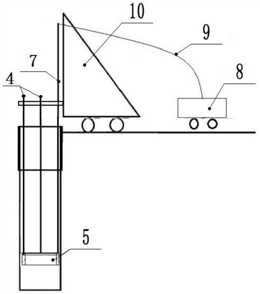
[0029] c. Check whether the component connection and the grouting channel are smooth: check whether the connection between the grouting machine 8 and the grouting pipe 7, the grouting pipe 7 and the annular grouter 5, the lifting rod 4 and the annular grouter 5 is tight; Check whether the grouting channel is unobstructed by pre-compressing a certain amount of grout, and...

Embodiment 2

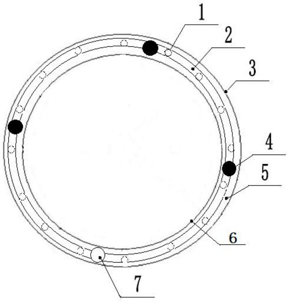
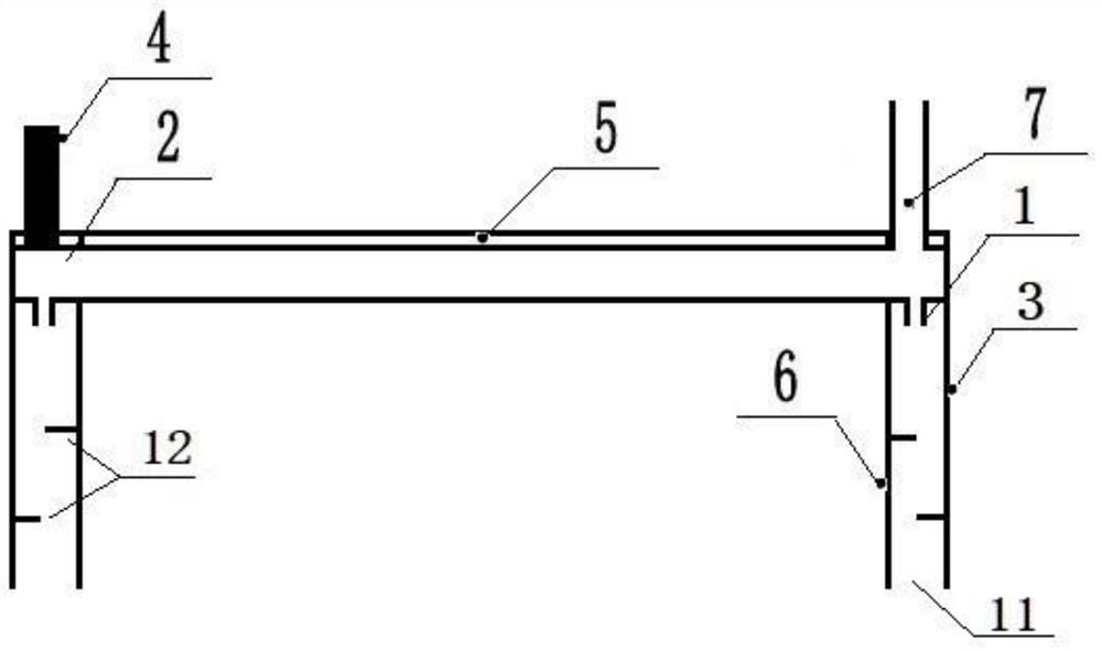
[0040] A device for synchronously forming the anticorrosion protection layer of bored piles for implementing the method described in Example 1, comprising an annular grouting device 5, a lifting rod 4, a grouting pipe 7 and a nozzle 1; the upper end of the grouting pipe 7 passes through The grout delivery pipe 9 is connected with the grouting machine 8, the lower end is fixedly connected with the annular grouter 5, and communicates with the annular pipe 2 provided inside the annular grouter 5; the bottom circumference of the annular pipe 2 is provided with a plurality of nozzles 1 , the nozzle 1 communicates with the inside of the annular pipe 2, and the bottom of the annular grouter 5 is a grout outlet 11, and the anti-corrosion slurry is injected into the grouting pipe 7 through the grouting machine 8, and thus enters the annular grouter 5, and the sprayer 1. Pour anti-corrosion grout into the hole; the lifting rod 4 is connected with the annular grouter 5 for lifting the ann...


PUM


Abstract

The invention belongs to the technical field of building pile foundations, and particularly relates to a synchronous forming method for a cast-in-situ bored pile anti-corrosion protection layer, which solves the problem that pile foundations in saline soil and other areas do not have effective anti-corrosion measures at present, and comprises the following steps: performing conventional cast-in-situ bored pile pore-forming work; preparing an anti-corrosion protection layer slurry material: preparing the anti-corrosion protection layer slurry material when underwater concrete is prepared to be poured; lowering an annular grouting device: lowering the annular grouting device to the bottom of the hole through lifting equipment while lowering the reinforcement cage; in the lifting grouting stage, after the underwater concrete is poured, lifting grouting is carried out immediately, and grouting is carried out while vibration lifting is carried out till the pile top and pile body concrete and an anti-corrosion protection layer are cured at the same time; the pile body anti-corrosion protection layer effectively improves the corrosion resistance of the pile foundation, improves the bearing capacity of the pile foundation, improves the durability of concrete and prolongs the service life of a bridge. The method has the advantages of simple principle, high efficiency, rapidness, remarkable anti-corrosion effect and the like.

Description

technical field [0001] The invention belongs to the technical field of building pile foundations, and in particular relates to a method for synchronously forming anticorrosion protection layers of bored cast-in-place piles. Background technique [0002] Bored cast-in-situ pile refers to the pile foundation formed by mechanically drilling holes in the foundation soil at the engineering site, placing steel cages in them, and pouring concrete. It is widely used in construction engineering, road and bridge engineering, and municipal engineering. With the construction of a large number of high-grade highways in our country, higher and higher requirements are put forward for the safety and durability of bridges. However, in Qinghai, Liaoning and coastal areas where saline soil is distributed, due to the presence of SO in water and soil, 4 2- , Mg 2+ , Cl - Such harmful particles will corrode the pile foundation concrete, and the low temperature climate and freeze-thaw effect w...

Claims


Application Information

Patent Timeline
Patent Type & Authority Applications(China)
IPC IPC(8): E02D5/34E02D15/04
CPCE02D5/34E02D15/04
Inventor 贾富贵黄杰井浩范奔奔范颖颖尹萍
Owner 黄杰
Learn More