Light beam direction calibration method of optical measuring head in spectrum confocal measurement system

A measurement system and spectral confocal technology, which is applied in the field of beam calibration of the optical probe of the spectral confocal measurement system, can solve the problem that the direction of the beam is not perpendicular to the surface of the measured object, etc., so that the calibration method is simple and easy to operate, reducing difficulty, The effect of improving robustness

Active Publication Date: 2021-12-03
HEFEI INSTITUTES OF PHYSICAL SCIENCE - CHINESE ACAD OF SCI
View PDF6 Cites 0 Cited by
  • Summary
  • Abstract
  • Description
  • Claims
  • Application Information

AI Technical Summary

Problems solved by technology

[0005] The present invention aims to solve the shortcomings of the above-mentioned prior art, and proposes a method for calibrating the beam direction of the optical probe in the spectral confocal measurement system, in order to solve the problem of the beam direction of the optical probe of the spectral confocal measurement system and the measured The problem that the surface of the object is not vertical can avoid the introduction of the system error of inclination angle in the system calibration, improve the measurement accuracy of the system, and at the same time realize the self-calibration of the beam direction during use

Method used


Image

  • Light beam direction calibration method of optical measuring head in spectrum confocal measurement system
  • Light beam direction calibration method of optical measuring head in spectrum confocal measurement system
  • Light beam direction calibration method of optical measuring head in spectrum confocal measurement system

Examples


Embodiment Construction

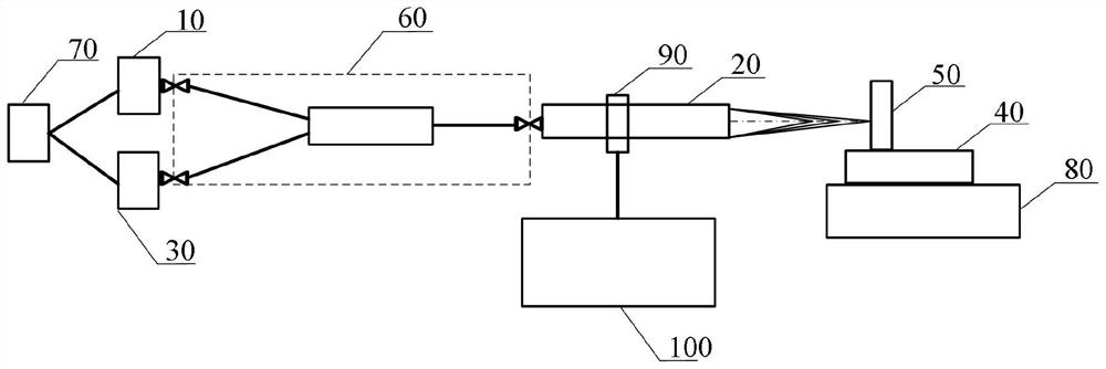
[0030] In this example, if figure 1 As shown, the spectral confocal measurement system is provided with an optical probe 20 through a fixture 90 on a four-axis precision translation stage 100, and the beam receiving end of the optical probe 20 is connected to the light source 10 and the spectrometer 30 through a Y-shaped fiber coupler 60, respectively. connected, and the controller 70 controls the light source 10 and the spectrometer 30; the beam dispersion end of the optical probe 20 faces the surface of the object to be measured 50 on the precision linear displacement stage 40, and the precision linear displacement stage 40 is placed on the rotary table 80 ;

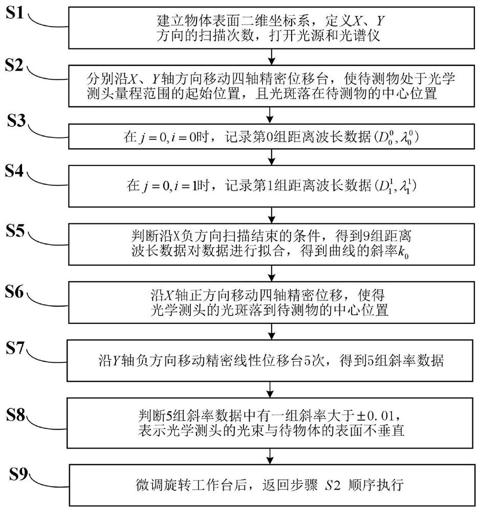
[0031] A beam direction calibration method of an optical probe in a spectral confocal measurement system, such as image 3 shown, including the following steps:

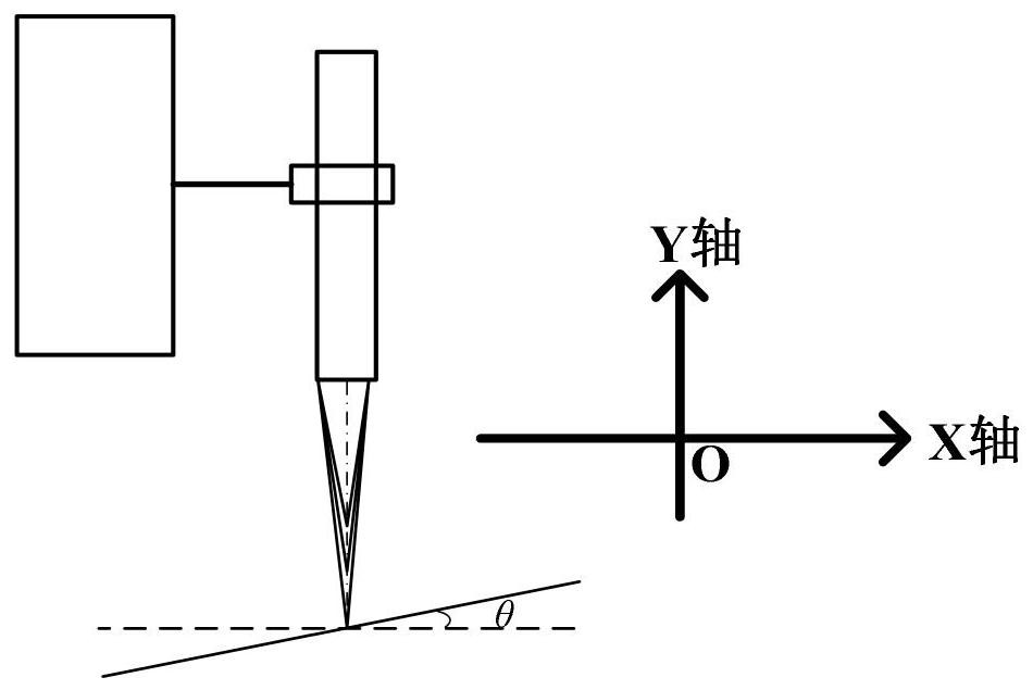
[0032] Step S1, taking the central position of the object to be measured 50 as the origin, the direction perpendicular to the surface of the object to be m...


PUM


Abstract

The invention discloses a light beam direction calibration method of an optical measuring head in a spectrum confocal measurement system, which comprises the following steps of: constructing the spectral confocal measurement system, establishing a two-dimensional coordinate system of the surface of an object, coarsely adjusting a rotary worktable to enable the optical probe to be preliminarily vertical to the surface of the object to be measured, scanning the surface of the object to be measured in the X-axis direction, performing curve fitting on the scanning times and the obtained wavelength information of the surface of the to-be-measured object to obtain slope information, and judging the vertical information of the optical measuring head and the surface of the to-be-measured object through the slope; carrying out multiple times of measurement at different positions in the measurement range of the optical measuring head, so that multiple groups of slope information are obtained, and the multiple groups of slope information are judged to improve the calibration precision; and finally, according to the result, determining whether to adjust the light beam direction of the optical measuring head to calibrate the light beam direction of the optical measuring head by finely adjusting the rotary workbench. According to the invention, the system error can be reduced, the measurement precision of the system can be improved, and the self-calibration of the light beam direction can be realized in the use process.

Description

technical field [0001] The invention relates to the technical field of non-contact optical precision measurement, in particular to a beam calibration method for an optical measuring head of a spectral confocal measurement system. Background technique [0002] The spectral confocal measurement system is a non-contact high-resolution optical precision measurement system, which has the characteristics of high measurement accuracy, fast measurement speed, no influence of ambient light sources, and no temperature and energy generated during the measurement process. The spectral confocal measurement system is widely used in various high-precision measurement occasions with different requirements, from the measurement and analysis of the fine structure, shape and texture roughness of the object surface to the online quality inspection, process control, reverse engineering and laboratory research in the industrial environment High-precision equipment for occasions, etc. [0003] Th...

Claims


Application Information

Patent Timeline
Patent Type & Authority Applications(China)
IPC IPC(8): G01M11/02
CPCG01M11/0221
Inventor 洪津吴洋
Owner HEFEI INSTITUTES OF PHYSICAL SCIENCE - CHINESE ACAD OF SCI
Why Eureka
Try Eureka