
Self-adaptive control method of power generation internal combustion engine applied to various gas sources

An adaptive control and internal combustion engine technology, applied in engine control, electrical control, combustion engine, etc., can solve the problems of high methane and hydrogen, large difference in calorific value, etc., and achieve low-emission and reasonable utilization, reliable and reasonable utilization Effect

Active Publication Date: 2021-12-07
TIANJIN UNIV
View PDF12 Cites 2 Cited by
  • Summary
  • Abstract
  • Description
  • Claims
  • Application Information

AI Technical Summary

Problems solved by technology

[0005] And because the calorific value of methane and hydrogen are both high, the difference in calorific value is large, especially the flame propagation speed of the two is different, which leads to the different requirements of methane and hydrogen for the optimal air-fuel ratio, so different proportions of methane and hydrogen are mixed. The need for air-fuel ratio needs to be redesigned to take into account the difference between the two, and the current natural gas generator does not take this into account

Method used


Image

  • Self-adaptive control method of power generation internal combustion engine applied to various gas sources
  • Self-adaptive control method of power generation internal combustion engine applied to various gas sources
  • Self-adaptive control method of power generation internal combustion engine applied to various gas sources

Examples


Embodiment Construction

[0034] The technical solutions in the embodiments of the present invention will be apparent from the drawings in the embodiment of the present invention. The described embodiments are merely the embodiments of the invention, not all of the embodiments. Based on the embodiments of the present invention, all other embodiments obtained by those of ordinary skill in the art are in the range of the present invention without making creative labor premise.

[0035] The direction and position term mentioned herein, such as the left, right, above, below, and the like, are merely or in the direction or position of the accompanying drawings. Thus, the direction and location terms used are used to illustrate and understand the present invention, and are not limited to the scope of the invention.

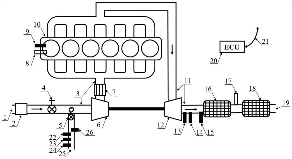
[0036] Append figure 1 The present invention is an adaptive control system suitable for a plurality of gas sources, including intake systems, exhaust gas turbine booster systems, exhaust rear proces...


PUM


Abstract

The invention discloses a self-adaptive control method of a power generation internal combustion engine applied to various gas sources. The self-adaptive control method comprises the following steps: detecting the concentrations of methane, hydrogen and carbon dioxide and gas mass flow in gas sources through a methane concentration sensor, a hydrogen concentration sensor, a carbon dioxide concentration sensor and a gas mass flow meter, and inputting the concentrations of methane, hydrogen and carbon dioxide and the gas mass flow into an ECU; matching an air-fuel ratio through ECU according to a self-adaptive air-fuel ratio MAP obtained by an embedded algorithm, and controlling ignition time according to the rotating speed and the equivalent torque of the total heat value of the incoming flow gas through ECU; and controlling a gas inlet system, a gas supply and injection system, an ignition system and a turbocharging system based on pure gas mass flow in the incoming flow gas, the carbon dioxide concentration and the air-fuel ratio and achieving self-adaptive combustion of the engine. An oxygen sensor feeds back and corrects the air-fuel ratio; a knock sensor feeds back and corrects ignition time; and a temperature sensor and a nitrogen oxide concentration sensor control urea injection of a post-treatment system. According to the self-adaptive control method of the power generation internal combustion engine applied to various gas sources, the efficient and stable combustion power generation process of enabling the engine to be adapted to different gas sources can be realized; and ultra-low emission is only generated.

Description

Technical field [0001] The present invention relates to the field of engine, and more particularly to an internal combustion engine adaptive control method suitable for use in a plurality of gas sources. Background technique [0002] The internal combustion engine is widely used in the field of power generation due to high economics, wide reliability and reliability, and makes the motor run by fixed engine speed, adjusting torque to achieve power generation power, with the continuous upgrade of internal combustion engine emission regulations and carbon The emergence of new goals of peaks, carbon, and also due to national energy structural adjustment and environmental requirements, the use of biogas, industrial exhaust gas, and gas gas distributed internal combustion motors should also be born, but each generator can only utilize The respective gas sources are unable to adapt to a large change in gas concentration. [0003] The engine realizes the stable operation of the power gen...

Claims


Application Information

Patent Timeline
Patent Type & Authority Applications(China)
IPC IPC(8): F02B63/04F02B77/00F02B77/08F02D43/00F02D45/00
CPCF02B63/04F02B77/00F02B77/08F02B77/085F02D43/00F02D45/00Y02T10/30
Inventor 郑尊清李金成尧命发王浒刘海峰
Owner TIANJIN UNIV
Learn More