Millimeter wave dielectric resonator antenna module and communication equipment

A dielectric resonator and antenna module technology, applied in resonant antennas, antennas, electrical short antennas, etc., can solve the problems of DRA influence and obvious influence on the performance of feeder structure antennas, achieve low machining accuracy, reduce sensitivity, realize Effects of space feed

Pending Publication Date: 2021-12-07
SHENZHEN SUNWAY COMM
View PDF0 Cites 0 Cited by
  • Summary
  • Abstract
  • Description
  • Claims
  • Application Information

AI Technical Summary

Problems solved by technology

These four feeding forms have high processing accuracy requirements in the millimeter wave frequency band. In addition, the processing error of the feeding structure has a significant impact on the performance of the antenna, and the relative position accuracy requirements of the feeding structure and DRA (dielectric resonator) Also very high (significant sensitivity to bit errors), can have a fundamental impact on DRA

Method used


Image

  • Millimeter wave dielectric resonator antenna module and communication equipment
  • Millimeter wave dielectric resonator antenna module and communication equipment
  • Millimeter wave dielectric resonator antenna module and communication equipment

Examples


Embodiment 1

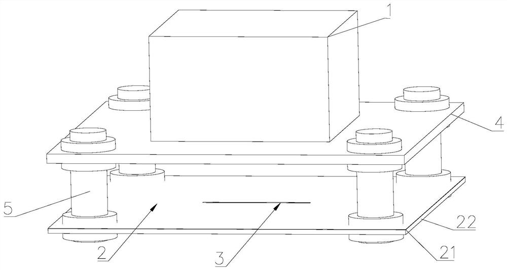
[0055] Please refer to Figure 1-3 , a millimeter-wave dielectric resonator antenna module in this embodiment, including a dielectric resonator 1 and an antenna ground 2;

[0056] The dielectric resonator 1 is arranged on one side of the antenna ground 2, and the dielectric resonator 1 is within the antenna near-field area of ​​the antenna ground 2, and the dielectric resonator 1 and the antenna ground 2 there is a gap between

[0057] A feeding structure 3 is provided at a position corresponding to the antenna ground 2 and the dielectric resonator 1;

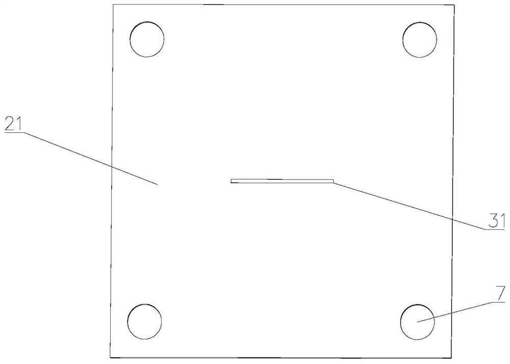
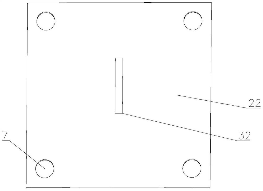
[0058] Specifically, such as figure 1 As shown, the antenna ground 2 includes a metal ground 21 and a dielectric substrate 22;

[0059] The dielectric resonator 1 is located on one side of the metal ground 21;

[0060] The dielectric substrate 22 is located on the other side of the metal ground 21;

[0061] Such as figure 2 , 3 As shown, the feed structure 3 includes a rectangular slot 31 and a microstrip line 32;

[006...

Embodiment 2

[0066] Please refer to Figure 1-12 , the difference between this embodiment and the first embodiment is that the specific structure of the dielectric resonator, the placement plate and the support is defined:

[0067] Specifically, the interval is 0.25-0.5 times the wavelength corresponding to the working frequency of the antenna;

[0068] The dielectric constant of the dielectric resonator 1 is 2.5-5;

[0069] Wherein, the shape of the dielectric resonator 1 is not limited, but the shape of the dielectric resonator 1 must be able to excite the antenna radiation mode;

[0070] In an optional implementation manner, the dielectric constant of the dielectric resonator 1 is 2.5, the shape of the dielectric resonator 1 is a cuboid, the length and width are 10 mm, and the height is 5.65 mm, such as figure 1 shown;

[0071] Such as figure 1 , 4 As shown, it also includes a placement plate 4 and a support 5;

[0072] The placement plate 4 is arranged on the side of the dielectr...


PUM


Abstract

The invention discloses a millimeter wave dielectric resonator antenna module. The millimeter wave dielectric resonator antenna module comprises a dielectric resonator and an antenna ground; the dielectric resonator is arranged on one side of the antenna ground, the dielectric resonator is located in an antenna near-field region range of the antenna ground, and an interval exists between the dielectric resonator and the antenna ground; and a feed structure is arranged at the position, corresponding to the dielectric resonator, of the antenna ground, the dielectric resonator is arranged in the antenna near-field area range of the antenna ground, a gap is formed between the dielectric resonator and the antenna ground, the antenna ground can feed the dielectric resonator through the antenna near-field area, space feed is achieved, the feed mode is simple, and the interval only needs to ensure that the dielectric resonator is within the antenna near-field region range of the antenna ground. The processing precision required by the feed mode is low, the influence of the processing error on the antenna is low, and thus the sensitivity of the antenna to the processing error of the feed structure is reduced.

Description

technical field [0001] The invention relates to the technical field of antennas, in particular to a millimeter-wave dielectric resonator antenna module and communication equipment. Background technique [0002] The dielectric resonator antenna is an antenna with excellent performance, which can be used in the mobile terminal of 5G (5th-Generation, fifth-generation mobile communication technology) millimeter wave. The feeding of the current standard dielectric resonator antenna is in four forms: slot coupling feeding, microstrip feeding, CPW feeding (Cost Per Wear, coplanar waveguide) and probe feeding. These four feeding forms have high processing accuracy requirements in the millimeter wave frequency band. In addition, the processing error of the feeding structure has a significant impact on the performance of the antenna, and the relative position accuracy requirements of the feeding structure and DRA (dielectric resonator) Also very high (significant sensitivity to bit e...

Claims


Application Information

Patent Timeline
Patent Type & Authority Applications(China)
IPC IPC(8): H01Q9/04H01Q1/50H01Q1/48H01Q1/24H01Q1/00
CPCH01Q9/0485H01Q1/50H01Q1/48H01Q1/241H01Q1/002H01Q1/243
Inventor 赵伟
Owner SHENZHEN SUNWAY COMM
Why Eureka
Try Eureka