Storage device for cyclic impurity removal of diethyltoluenediamine
A diethyltoluenediamine and storage device technology, which is applied in the field of diethyltoluenediamine cyclic impurity removal storage device, can solve the problems of chemical property influence, low catalyst impurity removal efficiency, etc., and achieve the effect of chemical property stability
- Summary
- Abstract
- Description
- Claims
- Application Information
AI Technical Summary
Problems solved by technology
Method used
Image
Examples
Embodiment 1
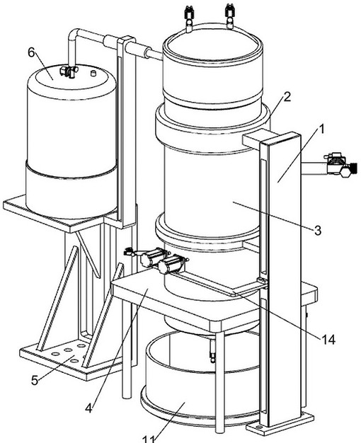
[0033] Such as Figure 1-3 As shown, a storage device for circulating and removing impurities of diethyltoluenediamine includes installation side frame column 1, tank body fixing ring 2, storage tank body 3, fixed bottom frame 4, installation platform 5, exhaust isolation feeding System 6, precipitation stratification system 7, precipitation collection gas exchange system 8, first pipeline connection component 9, conical collection chassis 12, second pipeline connection component 13, motor frame plate 14 and seventh pipeline connection component 15; installation side A tank fixing ring 2 is welded on the left top and the left middle of the frame column 1; a storage tank 3 is affixed to the inside of the two tank fixing rings 2; a fixed bottom frame 4 is affixed to the bottom of the outer surface of the storage tank 3 The top of the storage tank 3 is connected with an exhaust isolation feeding system 6; the left bottom of the exhaust isolation feeding system 6 is connected with...
Embodiment 2
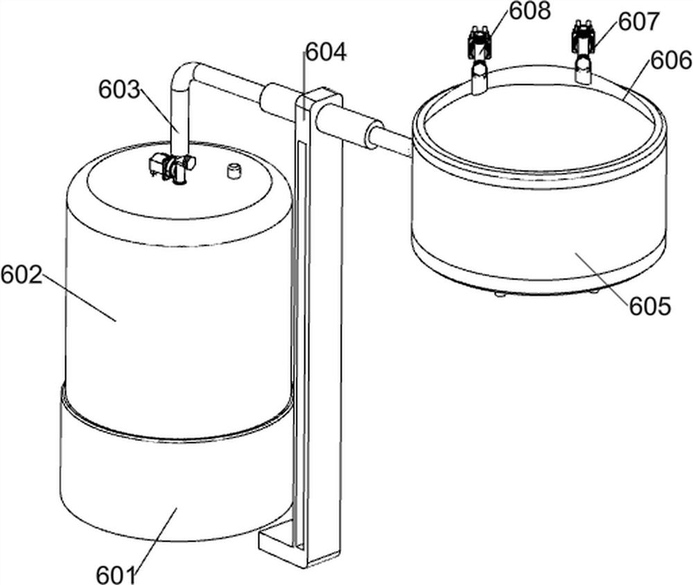
[0040] On the basis of Example 1, such as Figure 4-6 As shown, the exhaust gas isolation feeding system 6 includes a socket seat 601, a nitrogen storage tank 602, a third pipeline connection assembly 603, a pipe rack plate 604 and an exhaust liquid storage assembly; the top of the storage tank 3 is installed with an exhaust liquid storage Components; the top of the installation platform 5 is equipped with a socket seat 601; the inner side of the socket seat 601 is fixedly connected with a nitrogen storage tank 602; The frame plate 604; the top of the pipe frame plate 604 is sleeved in the middle of the outer surface of the third pipe connecting component 603; the third pipe connecting component 603 is fixedly inserted into the exhaust liquid storage component.
[0041] The third pipeline communication component 603 is controlled to be opened, and then the nitrogen inside the nitrogen storage tank 602 enters the exhaust liquid storage component along the third pipeline communi...
Embodiment 3
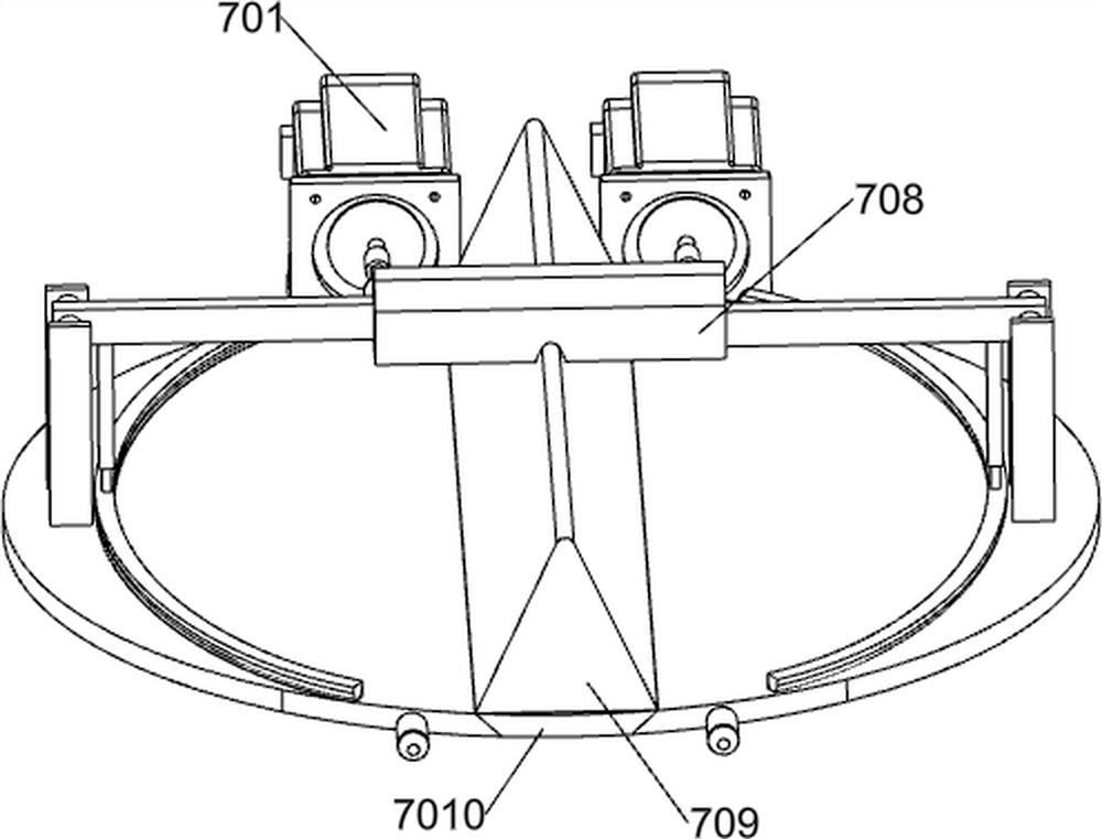
[0045] On the basis of Example 2, such as Figure 7-8 As shown, the precipitation layering system 7 includes a power motor 701, an installation insertion rod 702, a side opening and closing layering plate 703, a fixed bearing sleeve 704, a bearing frame plate 705, a rotating shaft rod 706, a sliding insertion rod 707, and an insertion sliding sleeve Rod 708, triangular settling guide column 709, middle joint plate 7010 and sediment removal assembly; motor frame plate 14 top left bolt is connected with power motor 701; storage tank body 3 front side middle left part is rotationally connected with installation inserting rod 702 ; The installation rod 702 is fixedly connected to the output shaft of the power motor 701; the outer surface of the installation rod 702 is fixedly sleeved with a side opening and closing layered plate 703; the rear side of the installation rod 702 is rotationally connected with a fixed bearing sleeve 704; the fixed bearing The sleeve 704 is fixedly plug...
PUM
 Abstract
Description
Claims
Application Information
 - R&D
- Intellectual Property
- Life Sciences
- Materials
- Tech Scout
- Unparalleled Data Quality
- Higher Quality Content
- 60% Fewer Hallucinations
Browse by: Latest US Patents, China's latest patents, Technical Efficacy Thesaurus, Application Domain, Technology Topic, Popular Technical Reports.
© 2025 PatSnap. All rights reserved.Legal|Privacy policy|Modern Slavery Act Transparency Statement|Sitemap|About US| Contact US: help@patsnap.com


