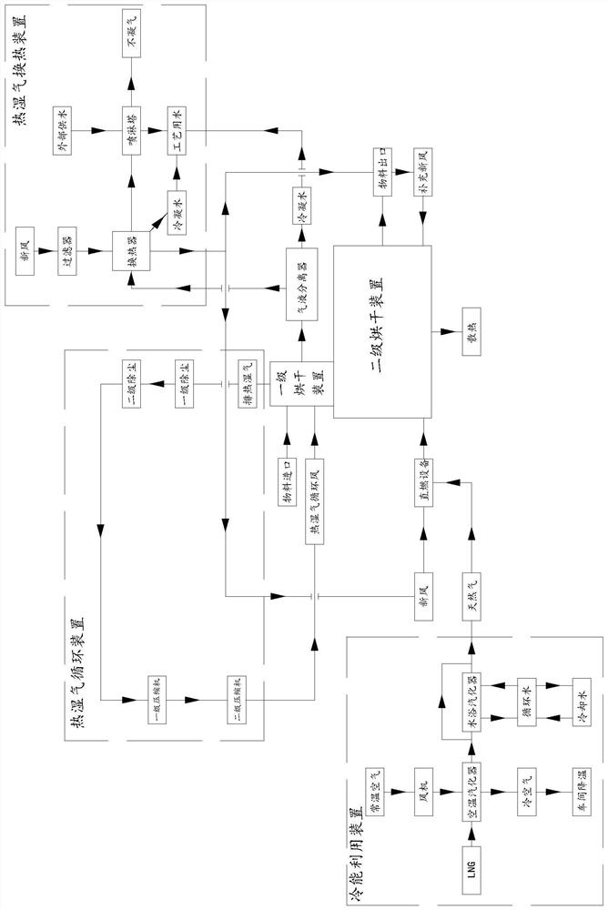
Green energy-saving fuel gas direct combustion drying system

A drying system and gas technology, applied in the direction of drying machine combination, drying solid materials, drying gas arrangement, etc., can solve the problems of material quality not meeting the requirements, low heat utilization rate, pollution of the atmospheric environment, etc., to protect the environment, Effect of reducing power consumption and production cost

Pending Publication Date: 2021-12-10
青岛创客智造机械设备有限公司
View PDF6 Cites 1 Cited by
  • Summary
  • Abstract
  • Description
  • Claims
  • Application Information

AI Technical Summary

Problems solved by technology

[0002] At present, basically all users adopt a single drying mode. The entire drying process from high-moisture wet materials to low-moisture finished products is carried out in one kind of drying equipment. In fact, each material has its own unique drying curve, and this A single drying mode will inevitably cause problems such as low heat utilization, long drying time, and material quality that cannot meet the requirements.
A large amount of waste gas, waste heat and dust are directly discharged into the atmosphere during the drying process of materials, which not only pollutes the atmospheric environment, but also causes a waste of energy. Sensible heat and absorption of heat from the external atmosphere to realize the gasification function, and all cold energy is wasted

Method used


Image

  • Green energy-saving fuel gas direct combustion drying system

Examples


Embodiment Construction

[0019] Below in conjunction with accompanying drawing and embodiment, the present invention will be further described:

[0020] In the present invention, unless otherwise expressly specified and limited, the terms "installed", "connected", "connected", "fixed" and other terms should be understood in a broad sense, for example, it may be a fixed connection or a detachable connection , or integrated; it can be directly connected or indirectly connected through an intermediate medium, and it can be the internal connection of two elements or the interaction relationship between the two elements. For those of ordinary skill in the art, the specific meanings of the above terms in the present invention can be understood according to specific situations.

[0021] In the description of the present invention, it should be understood that the terms "center", "length", "upper", "lower", "front", "rear", "left", "right", "vertical", The orientation or positional relationship indicated by ...


PUM


Abstract

The invention relates to the field of silica gel drying, in particular to a green energy-saving fuel gas direct-fired drying system. The green energy-saving fuel gas direct-fired drying system comprises a first-stage drying device and a second-stage drying device, wherein the first-stage drying device is provided with a material inlet, the second-stage drying device is provided with a material outlet, and materials are continuously conveyed to the second-stage drying device from the first-stage drying device; and direct combustion equipment is communicated with the secondary drying device, hot air generated by the direct combustion equipment sequentially passes through the second-stage drying device and the first-stage drying device, serves as hot moisture, passes through the first-stage drying device in an indirect contact manner after passing through a hot moisture circulating device and then is communicated with a hot moisture heat exchange device used for heating fresh air, and the fresh air is communicated with the direct combustion equipment. According to the green energy-saving fuel gas direct-fired drying system, the mode that the two or more drying devices are combined is adopted for drying the materials in sequence, so that the heat utilization rate and the drying efficiency are improved; and an air temperature type vaporizer is transformed, a water bath circulation type vaporizer is additionally arranged, and cold air and cold water are generated through cold energy generated in the LNG gasification process to replace an air conditioner and a refrigerating machine.

Description

technical field [0001] The invention relates to the field of silica gel drying, in particular to a green energy-saving gas direct combustion drying system. Background technique [0002] At present, basically all users use a single drying mode. The entire drying process from high-moisture moisture materials to low-moisture products is carried out in one drying equipment. In fact, each material has its own unique drying curve. A single drying mode will inevitably cause problems such as low utilization of heat, long drying time, and material quality that cannot meet the requirements. During the drying process of materials, a large amount of waste gas, waste heat and dust are directly discharged into the atmosphere, which not only pollutes the atmospheric environment, but also causes waste of energy; The gasification function is realized by sensible heat and absorbing the heat of the external atmosphere, and all the cold energy is wasted. SUMMARY OF THE INVENTION [0003] Th...

Claims


Application Information

Patent Timeline
Patent Type & Authority Applications(China)
IPC IPC(8): F26B20/00F26B21/00F26B21/04F26B23/02F26B25/00
CPCF26B20/00F26B21/001F26B21/04F26B23/02F26B25/005
Inventor 李永兆李斌杰
Owner 青岛创客智造机械设备有限公司
Why Eureka
Try Eureka