Supercharge Your Innovation With Domain-Expert AI Agents!

Method for optical nondestructive detection of surface-interface conversion of single nanoparticles

A nanoparticle, surface interface technology, applied in the field of single nanoparticle imaging and analysis, can solve the problems that particle analysis cannot be applied in situ, the size of nanoparticles is small, and it is difficult to achieve high-throughput analysis of nanoparticles

Active Publication Date: 2021-12-10
UNIV OF SCI & TECH OF CHINA
View PDF3 Cites 0 Cited by
  • Summary
  • Abstract
  • Description
  • Claims
  • Application Information

AI Technical Summary

Problems solved by technology

However, there are many challenges in tools and methods to understand the surface-interface transformation process of nanoparticles: 1) the small size of nanoparticles makes detection difficult; 2) the existing electrochemical analysis methods do not have spatial resolution, and it is difficult to realize the high-throughput analysis; while electron microscopic imaging (such as SEM, TEM, etc.) can only characterize nanoparticles under dry conditions, and cannot be applied to particle analysis under solution conditions in situ; 3) label-free recognition of particles is also the One of the challenges that the field is currently facing. For example, although dark-field imaging technology has the advantage of being label-free, it cannot specifically identify particles and has specific restrictions on the types of imaging particles. Although single-molecule fluorescence imaging technology can meet the specific recognition of particles Required, but needs to be labeled with a specific fluorescent molecule
Therefore, it is difficult for existing methods to accurately analyze and identify the surface-interface transformation process of nanoparticles in situ and in real time.

Method used


Image

  • Method for optical nondestructive detection of surface-interface conversion of single nanoparticles
  • Method for optical nondestructive detection of surface-interface conversion of single nanoparticles
  • Method for optical nondestructive detection of surface-interface conversion of single nanoparticles

Examples


Embodiment 1

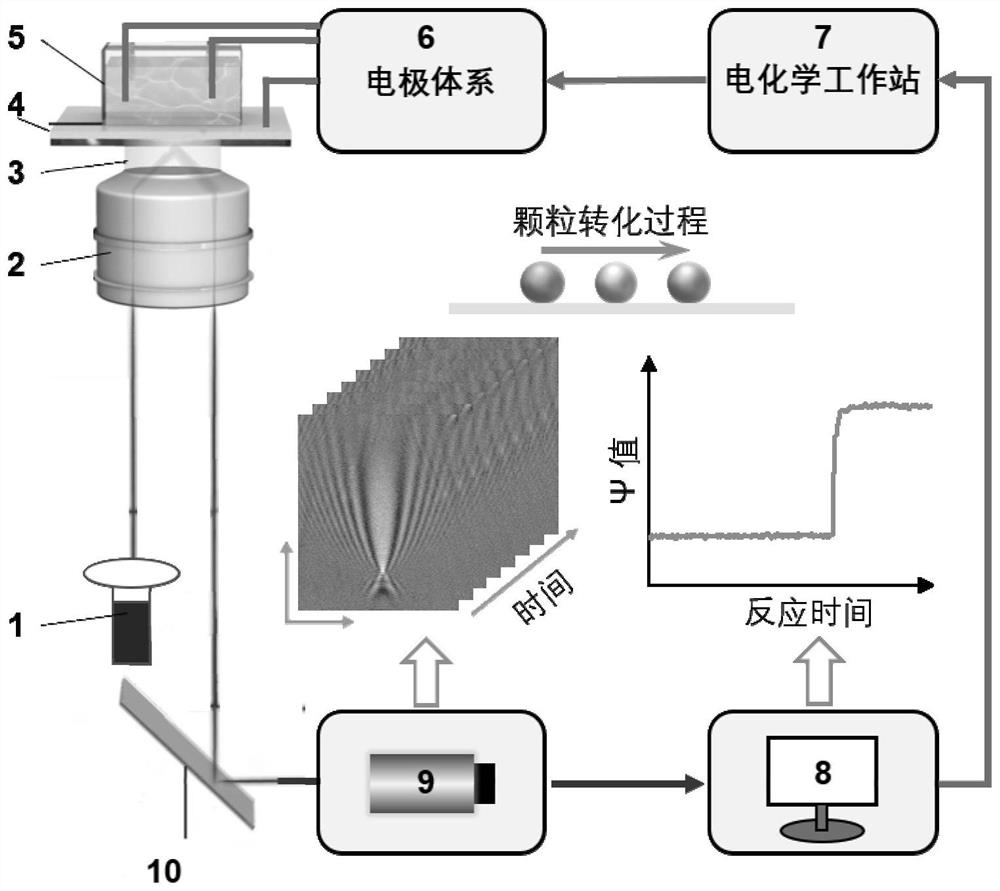
[0035] Build a single nanoparticle surface-interface conversion optical imaging system, the system structure is as follows: figure 1 shown, including:

[0036] Laser light source 1, objective lens 2, mirror oil 3, gold-coated glass sheet 4, sample cell 5, reaction condition control module including electrode system 6 and electrochemical workstation 7, software processing module 8, camera acquisition system 9, mirror 10.

[0037] The laser light source 1 is used to introduce monochromatic light of a fixed wavelength into the surface plasmon imaging and adjust the light intensity of the laser to meet the imaging requirements, and select a laser above 630nm as the excitation light source;

[0038] The objective lens 2 is used for optical signal amplification and imaging, and the immersion oil 3 is located between the optical microscopic magnifying objective lens and the gold film glass slide. The numerical aperture of the optical microscopic magnifying objective lens is greater t...

Embodiment 2

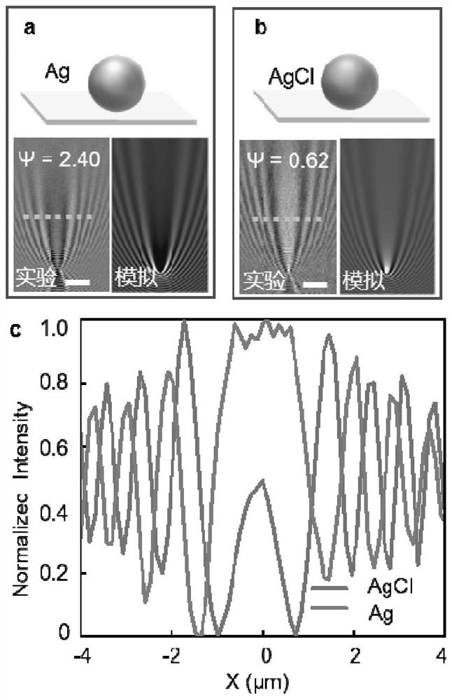
[0046] A method for optically non-destructively detecting the surface-interface transformation of a single nanoparticle, taking Ag and AgCl nanoparticles as an example, using the system built in Example 1, the detection method includes the steps:

[0047] (1) Synthesize target Ag and AgCl nanoparticles;

[0048] (2) Build a single-particle optical imaging device;

[0049] Add the solution containing the target particles into the reaction tank, collect time series images, and use the software processing module to analyze and obtain the characteristic phase parameter ψ of the nanoparticles as a function of time, so as to analyze the surface and interface transformation process of single nanoparticles.

[0050] Result analysis:

[0051] The experimental and simulation diagrams of the synthesized Ag nanoparticles are shown in figure 2 As shown in a, the diameter of Ag nanoparticles is 80nm. It can be seen from the imaging experiment diagram and theoretical simulation diagram th...

experiment example 1

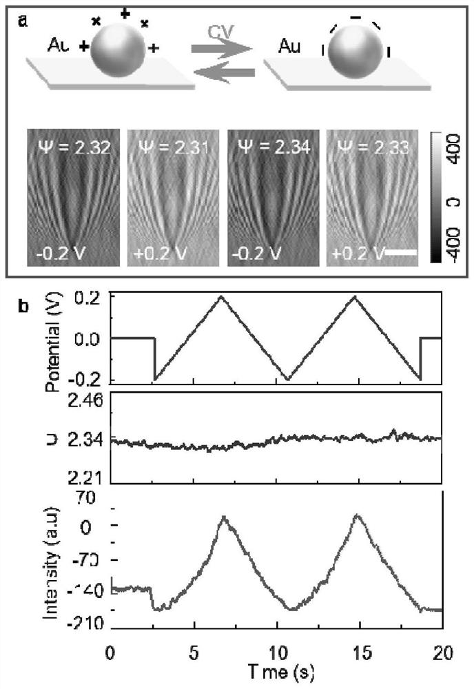
[0055] In order to test the label-free optical imaging that the method of the present invention can effectively resist background current signal interference, take Au nanoparticles as an example to verify, and the specific determination steps include:

[0056] (1) Synthesis of target Au nanoparticles;

[0057] (2) Build the device;

[0058] Add a certain concentration of KCl solution into the electrochemical cell, drop the solution containing the target Au particles into the sample cell, set the electrochemical parameters through the software processing module 8, collect time series images, and use the software processing module 8 to obtain the characteristics of the Au particles The value of the phase parameter ψ, while reading the particle intensity value directly on the image sequence.

[0059] Result analysis:

[0060] see test results image 3 as shown, image 3 a, Au nanoparticles do not undergo any compositional conversion in this potential interval (+0.2 V, −0.2 V)...


PUM

PropertyMeasurementUnit
Diameteraaaaaaaaaa
Diameteraaaaaaaaaa

Abstract

The invention relates to a method for optical nondestructive detection of surface-interface conversion of single nanoparticles. According to the method, a single nanoparticle surface-interface conversion optical imaging system is used for carrying out label-free identification on the surface-interface conversion process of a single nanoparticle, and the surface-interface conversion process of the particle is analyzed by calculating the change of the characteristic quantity of an intrinsic parameter psi of a target particle. The problem that an existing analysis method is difficult to carry out in-situ real-time accurate analysis and recognition on the surface-interface conversion process of the nanoparticles is solved, and the method has the advantages of being non-invasive, high in throughput, resistant to interference, wide in research object range and the like and can be used for research on surface-interface conversion, structure-function relation and the like of the nanoparticles under the single particle level, and the application of nano scientific imaging analysis is expanded.

Description

technical field [0001] The invention relates to a method for optically nondestructively detecting the surface-interface transformation of a single nanoparticle, belonging to the technical field of single nanoparticle imaging and analysis. Background technique [0002] The development of nanomaterials plays an important role in the progress of nanotechnology. Nanoparticles are playing an increasingly important role in the fields of catalysis, sensing, and biomedicine due to their size controllable and excellent performance. In recent years, due to the continuous development of the field of biochemical analysis, the requirements for the detection speed and sensitivity of biomolecules have been continuously improved. Nanoparticles, as a kind of nanomaterials that have been widely studied, are widely used in medicine and bioengineering. [0003] The surface interface is the transition region where one phase transitions to another. At the single-particle scale, understanding the...

Claims


Application Information

Patent Timeline
IPC IPC(8): G01N15/10
CPCG01N15/1031
Inventor 刘贤伟吴刚钱晨
Owner UNIV OF SCI & TECH OF CHINA
Features
  • R&D
  • Intellectual Property
  • Life Sciences
  • Materials
  • Tech Scout
  • Unparalleled Data Quality
  • Higher Quality Content
  • 60% Fewer Hallucinations
Learn More