
Data center machine room equipment layout method based on fluid mechanics simulation

A technology of data center and fluid mechanics, applied in electrical digital data processing, computer-aided design, design optimization/simulation, etc. Improvement of resource utilization, etc.

Active Publication Date: 2021-12-10
军事科学院系统工程研究院网络信息研究所
View PDF2 Cites 3 Cited by
  • Summary
  • Abstract
  • Description
  • Claims
  • Application Information

AI Technical Summary

Problems solved by technology

In this design process, designers seldom consider the influence of the uneven power consumption of the equipment installed and deployed in the actual data center on the utilization efficiency of the cold source of the air conditioner in the data center computer room, that is, when the cooling system capacity is a fixed value Under normal circumstances, the maximum power consumption of IT equipment that can be accommodated in the data center remains unchanged, and it is rarely considered that the layout optimization of IT equipment in the data center will improve the utilization rate of the cold source of the cooling system, and further affect the IT equipment installed and deployed in the data center computer room. Positive effect of capacity on total power consumption

Method used


Image

  • Data center machine room equipment layout method based on fluid mechanics simulation
  • Data center machine room equipment layout method based on fluid mechanics simulation

Examples


Embodiment Construction

[0032] The specific implementation manners of the present invention will be described in detail below in conjunction with the accompanying drawings.

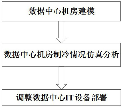
[0033] The embodiment of the present invention provides a data center computer room equipment layout method based on fluid dynamics simulation, including the following steps:

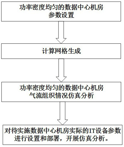
[0034] Step S1, using fluid mechanics simulation software (such as Fluent, 6SigmaRoom), to construct a data center computer room model according to the actual size of the data center and the layout of IT equipment in the computer room;

[0035] Step S2, setting the power consumption, size, and location parameters of the IT equipment, performing airflow organization simulation analysis on the data center computer room, and generating input and output temperature difference diagrams at different positions of each equipment cabinet in the data center computer room;

[0036] Step S3, adjusting the position of the IT equipment in the data center computer room ...


PUM


Abstract

The embodiment of the invention provides a data center machine room equipment layout method based on fluid mechanics simulation, relates to the technical field of data center machine room layout methods, and aims to improve the utilization efficiency of a data center refrigeration system and increase the capacity of data center machine room IT equipment power consumption. The method comprises the following steps of: constructing an equipment layout model in a data center machine room; carrying out modeling according to the overall layout of to-be-transformed data center machine room equipment, wherein the modeling content comprises the length, the width and the height of the data center machine room, the size, the position, the air supply and return position as well as the air supply and return temperature of an air conditioner in the data center machine room, and the size of a cabinet in the data center machine room; when an air flow organization mode of air supply under the floor is adopted, determining the height of the floor and an aperture ratio of a cold channel floor; performing air distribution simulation analysis on the IT equipment in the data center machine room; and adjusting the position of the IT equipment in the data center machine room according to the result of the airflow organization simulation analysis.

Description

technical field [0001] The invention relates to the technical field of data center computer room layout methods, in particular to a data center computer room equipment layout method based on fluid dynamics simulation. Background technique [0002] At present, the construction of data centers generally adopts the airflow organization method of closed cold aisles, and uses room-level air conditioners or inter-row air conditioners to provide cold sources. With the development and application of cloud computing, the cost of building a new data center for an enterprise is high and the necessity is insufficient. Generally, the transformation or expansion is based on the data center already built by the enterprise. However, the power supply and cooling system of the completed data center is difficult to transform, and the cost is high high. [0003] In the design of data centers, generally speaking, it is first necessary to determine the scale of the data center to be built and th...

Claims


Application Information

Patent Timeline
IPC IPC(8): G06F30/13G06F30/28G06F113/08G06F119/14
CPCG06F30/28G06F30/13G06F2119/14G06F2113/08
Inventor 刘志波谢永强杨雄军张凯宁希张云超李玉倩白皓陶妍丹
Owner 军事科学院系统工程研究院网络信息研究所
Learn More