High-precision numerical control phase shifter for K wave band and phase shifting method of high-precision numerical control phase shifter

A digitally controlled phase shifting, high-precision technology, applied in the field of phase shifters, can solve problems such as poor amplitude modulation, discontinuous phase shifting, and large phase shifting steps, and achieve system cost reduction, easy integration, and phase shifting steps small effect

Active Publication Date: 2021-12-10
成都明夷电子科技有限公司
View PDF20 Cites 1 Cited by
  • Summary
  • Abstract
  • Description
  • Claims
  • Application Information

AI Technical Summary

Problems solved by technology

With the development of modern electronic technology, A / D and D / A conversion are mainly used to realize digital phase shifting. The advantage of this phase shifter is that the phase shifting accuracy is high. The disadvantage is that the phase shift is discontinuous and discontinuous due to the limited digital control bits. Large chip area
[0003] The traditional digital control phase shifter has a discontinuous phase shift, that is, a large phase shift step, which is not conducive to use, resulting in limitations in application scenarios
At the same time, due to the high frequency band (18GHz-27GHz) of the K-band, the traditional phase shifter has a large insertion loss in this frequency band, poor amplitude modulation, and the disadvantages of a large chip area will also increase the cost.

Method used


Image

  • High-precision numerical control phase shifter for K wave band and phase shifting method of high-precision numerical control phase shifter
  • High-precision numerical control phase shifter for K wave band and phase shifting method of high-precision numerical control phase shifter

Examples


Embodiment 1

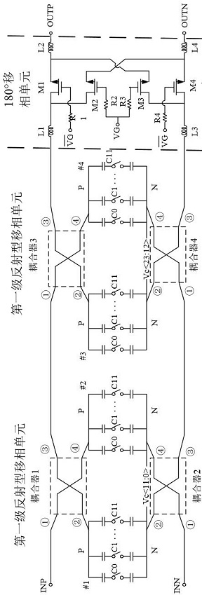
[0055] This embodiment proposes a high precision numerical control phase for k-band, connected to the INN input signal and the INP input signal, such as figure 1 , figure 2 As shown, a reflective phase shift module, a 180 ° phase shift unit, and a logic control circuit are shown.

[0056] The reflective phase shifting module includes two reflective phase shift units, respectively, a first stage reflective phase shift unit and a second-stage reflective phase shift unit, respectively;

[0057] The first stage reflective phase shift unit, the second stage reflective phase shift unit, and the 180 ° phase shift unit are sequentially connected; the first stage reflective phase shift unit is connected to the INN input signal and the INP input signal, respectively;

[0058] The logic control circuit includes a first stage control unit, a second level control unit, and a third level control unit;

[0059] The first stage control unit is a binary bit control code output unit, respectively, ...

Embodiment 2

[0064] This embodiment also proposes a phase shift method for a high-precision numerical control phase using a K-band, based on a high-precision numerical control phase in which the K band is used, including the following steps:

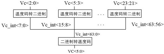
[0065] Step 1: Divide the binary bit control code output from the first stage control unit into two parts, partially output to the 180 ° phase shift unit for phase control, and the other part is transmitted to the second level control unit;

[0066] Step 2: Convert the received binary bit control code to a temperature code at the second stage control unit, and then split the converted temperature code and corresponding to the temperature code transfer module unit transmitted to the third stage control unit;

[0067] Step 3: Both the temperature code transfer module unit in the third stage control unit is divided into two groups, respectively, respectively, and the first-stage reflective phase shift unit and the second stage reflective phase shift unit ar...

Embodiment 3

[0071] In addition to the above-described embodiment 1, in order to better achieve the present invention, figure 1 , figure 2 As shown, the first stage reflective phase shift unit includes a first coupler, a second coupler, a first capacitive switch array, and a second capacitor switch array; the second stage reflective phase shift unit includes a third coupling. A fourth coupler, a third capacitive switch array and a fourth capacitor switch array; the first coupler, the second coupler, the third coupler, the fourth coupler are four coupler, the first A capacitor switch array, the second capacitance switch array third capacitor switch array and the fourth capacitive switch array contain 12 parallel switching capacitors;

[0072] The 1-coupled 1 interface connection of the INP input signal, 2 connecting the P end of the first capacitance switch array, 4 interface connects the P end of the second capacitor switch array;

[0073] The 1 interface of the second coupler is connected to ...


PUM


Abstract

The invention provides a high-precision numerical control phase shifter for a K wave band and a phase shifting method of the high-precision numerical control phase shifter. The method comprises the steps that three-stage phase shifting is divided, a first-stage reflection type phase shifting unit and a second-stage reflection type phase shifting unit are made to carry out 90-degree phase shifting, and then 180-degree phase shifting control is carried out through a 180-degree phase shifting unit; then a binary control code is converted into a control code for accurately controlling three-stage phase shift through a logic control circuit, so that high-precision and continuous phase shift control is realized, the defects of discontinuous K-band phase shift and large phase shift stepping under traditional phase shift are overcome through the arrangement; meanwhile, the phase shift control circuit can be realized by adopting conventional components, so that the cost is reduced, and the working efficiency is improved. According to the method, the cost is further greatly reduced under the condition that the phase shift stability is improved.

Description

Technical field [0001] The present invention belongs to the technical field of the phase shifter is applied to a wireless communication, and more particularly for a high-precision CNC K-band phase shifter and the phase shift method. Background technique [0002] Phase shifters are used in telecommunications, radar, missile attitude control, the accelerator, communication, instrumentation, and other fields. Wave will have an arbitrary phase shift in transmission conductive medium, a phase shifter for adjusting the phase shift device capable of generating waves during transmission. Due to different application scenarios will exist different transmission media, and thus results in a phase shift in which the transmission waves generated vary. Conventional phase shift of the phase shifter low precision, and the phase shift range is limited. With modern electronic technology, now mainly using A / D, D / A converter implemented digital phase shift, this phase shifter is shifting the adv...

Claims


Application Information

Patent Timeline
Patent Type & Authority Applications(China)
IPC IPC(8): H03H17/08H03H11/16
CPCH03H17/08H03H11/16
Inventor 袁小方刘成鹏姚静石毛毅
Owner 成都明夷电子科技有限公司
Why Eureka
Try Eureka