Efficient plasma cutting machine

A plasma cutting machine and plasma technology, applied in the directions of plasma welding equipment, welding/cutting auxiliary equipment, auxiliary welding equipment, etc., can solve the problems of reducing the quality of device processing, inaccurate metal cutting position, uneven surface of cutting parts, etc. Achieve improved accuracy, ease of cleaning, and reduced wear

Pending Publication Date: 2021-12-24
任伟
View PDF7 Cites 0 Cited by
  • Summary
  • Abstract
  • Description
  • Claims
  • Application Information

AI Technical Summary

Problems solved by technology

[0006] Aiming at the deficiencies of the prior art, the present invention provides a high-efficiency plasma cutting machine, which solves the problem that the position is easily shifted during cutting, causing the metal cutting position to be inaccurate or even damaged, and the surface of the cutting piece after cutting is uneven phenomenon, which reduces the quality of device processing

Method used


Image

  • Efficient plasma cutting machine
  • Efficient plasma cutting machine
  • Efficient plasma cutting machine

Examples


Embodiment 1

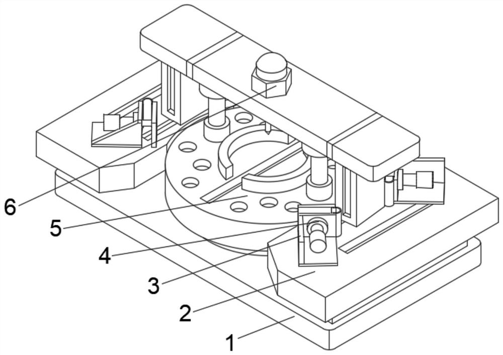
[0033] see Figure 1-2 , the present invention provides a technical solution: a high-efficiency plasma cutting machine, including a base plate 1, a cutting device 5 is fixedly connected to the top middle position of the base plate 1, a plasma cutter 6 is arranged at the top middle position of the cutting device 5, and the base plate 1 The top of the top is located on both sides of the cutting device 5 and is fixedly connected with the bearing plate 2, and the top of the bearing plate 2 is fixedly connected with the support seat 3 on both sides of the cutting device 5, and the side of the support seat 3 close to the cutting device 5 is provided with a positioning guide piece 4.

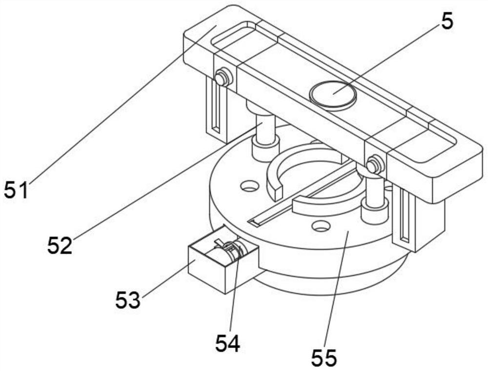
[0034] Wherein, the cutting device 5 includes a placing block 53, the bottom of the inner cavity of the placing block 53 is provided with a driving member 54, the right outer wall of the placing block 53 is fixedly connected with a stabilizing mechanism 55, and the middle position on both sides of the ...

Embodiment 2

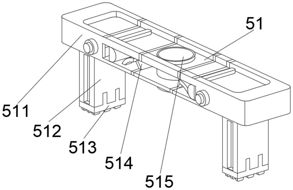
[0037] see Figure 1-4 , on the basis of Embodiment 1, the present invention provides a technical solution: component 1 of the moving mechanism 51 includes a fixed connection plate 512, the bottom of the fixed connection plate 512 is fixedly connected with a slider 513, and the top of the fixed connection plate 512 is fixedly connected There is a horizontal plate 511, the top middle of the horizontal plate 511 is fixedly connected with a fixed sleeve 515, and the top of the horizontal plate 511 is fixedly connected with a swing plate 514 on both sides of the fixed sleeve 515.

[0038] Among them, the first component of the stabilizing mechanism 55 includes a protective shell 551, the middle position of the inner cavity bottom of the protective shell 551 is fixedly connected with a stabilizing block 554, the top of the stabilizing block 554 is provided with a balance fixer 552, and the inner cavity bottom of the protective shell 551 is located Both sides of the block 554 are fi...

Embodiment 3

[0041] see Figure 1-6 , on the basis of Embodiment 1 and Embodiment 2, the present invention provides a technical solution: Component 2 of the moving mechanism 51 includes a balance beam d1, an internal solid block d3 is provided at the top middle of the balance beam d1, and the balance beam d1 The bottom is located on both sides of the inner solid block d3 with a positioning elevating rod d4, an auxiliary support d2 is fixedly connected between the top of the positioning elevating rod d4 and the balance beam d1, and the bottom of the positioning elevating rod d4 is fixedly connected with a moving plate d5.

[0042] Wherein, the second component of the stabilizing mechanism 55 includes a connection base t1, a transition piece t2 is fixedly connected to the top of the connection base t1, a casing t4 is fixedly connected to the top of the transition piece t2, and an overhanging plate t3 is arranged in the middle of the inner cavity top of the casing t4 , The top of the housing ...


PUM


Abstract

The invention discloses an efficient plasma cutting machine and relates to the technical field of metal cutting. The efficient plasma cutting machine comprises a bottom plate, a cutting device is fixedly connected to the middle position of the top of the bottom plate, a plasma cutter is arranged in the middle position of the top of the cutting device, and bearing plates are fixedly connected to the positions, located on the two sides of the cutting device, of the top of the bottom plate. Supporting bases are fixedly connected to the positions, located on the two sides of the cutting device, of the top of the bearing plate, and positioning guiding pieces are arranged on the sides, close to the cutting device, of the supporting bases. According to the efficient plasma cutting machine, during moving, abrasion of the surface of a moving mechanism is effectively reduced, the service life of the device is further prolonged, vibration generated during cutting of the device is effectively reduced, position deviation of a metal piece in the cutting process is not prone to being caused by vibration, and the situation that chippings enter a driving piece to damage a power piece can be avoided, a stabilizing mechanism can rotate slowly, so that the cutting angle of the device is further increased.

Description

technical field [0001] The invention relates to the technical field of metal cutting, in particular to an efficient plasma cutting machine. Background technique [0002] Plasma cutting with different working gases can cut all kinds of metals that are difficult to cut by oxygen cutting, especially for non-ferrous metals (stainless steel, aluminum, copper, titanium, nickel). Its main advantage is that it can cut metals with small thickness. At present, the plasma cutting speed is fast, especially when cutting ordinary carbon steel sheets, the speed can reach 5-6 times that of the oxygen cutting method, the cutting surface is smooth, the thermal deformation is small, and the heat-affected zone is less. [0003] According to a kind of metal cutting equipment disclosed in Chinese Patent No. CN112453541A, a propulsion structure is respectively provided between the fixed block and the workbench. Hold the drawer so that it moves toward the right side of the workbench with the protr...

Claims


Application Information

Patent Timeline
IPC IPC(8): B23K10/00B23K37/02B23K37/04B23K37/047
CPCB23K10/00B23K37/0252B23K37/0435B23K37/047
Inventor 任伟
Owner 任伟
Why Eureka
Try Eureka