Catadioptric imaging telescopic optical system

An optical system, catadioptric technology, applied in optics, optical components, instruments, etc., can solve problems such as unfavorable cost control, high processing cost, and inability to perform six-degree-of-freedom misalignment correction of the secondary mirror, achieving low manufacturing cost and good compatibility. high quality and good image quality

Active Publication Date: 2021-12-24
CHANGCHUN INST OF OPTICS FINE MECHANICS & PHYSICS CHINESE ACAD OF SCI
View PDF13 Cites 0 Cited by
  • Summary
  • Abstract
  • Description
  • Claims
  • Application Information

AI Technical Summary

Problems solved by technology

[0004] Common total reflection astronomical telescopes mostly adopt Cassegrain structure or R-C structure. Both common structures have aspheric reflectors, and the processing cost is relatively high, which is not conducive to cost control.
Moreover, the design of the existing telescopic optical structure does not take into account how to cooperate with the micro-displacement actuator, wavefront sensing and detection hardware system, and the image quality comprehensive testing system of the rear-end imaging unit system to form a complete spliced ​​space telescope. The principle verification prototype of orbital optical adjustment technology cannot carry out six-degree-of-freedom misalignment correction for the secondary mirror, as well as confocal and co-phase detection and adjustment for the spliced ​​primary mirror

Method used


Image

  • Catadioptric imaging telescopic optical system
  • Catadioptric imaging telescopic optical system
  • Catadioptric imaging telescopic optical system

Examples


Embodiment Construction

[0035] In order to make the object, technical solution and advantages of the present invention clearer, the present invention will be further described in detail below in conjunction with the accompanying drawings and specific embodiments. It should be understood that the specific embodiments described here are only used to explain the present invention, but not to limit the present invention.

[0036] The purpose of the present invention is to provide a catadioptric imaging telescopic optical system that has the main index system features of a spliced ​​telescope and can fully carry out the verification test of wavefront sensing and control technology. A catadioptric imaging telescopic optical system provided by the present invention will be described in detail below through specific embodiments.

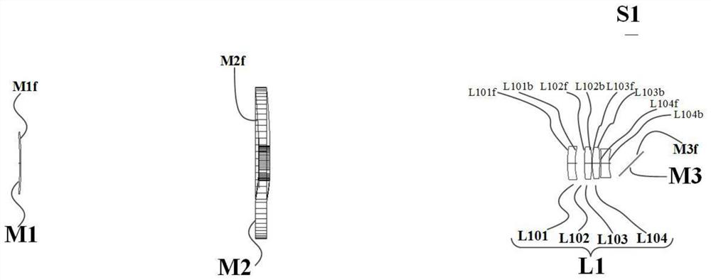
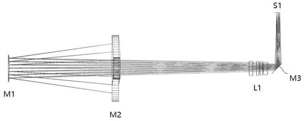
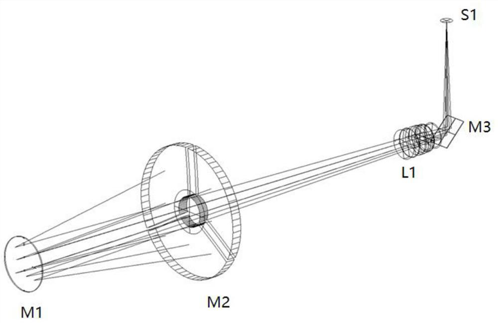
[0037] refer to figure 2 The optical path diagram of the catadioptric imaging telescopic optical system shown, the secondary mirror M1, the primary mirror M2, the lens assembly L...


PUM


Abstract

The invention belongs to the technical field of optical lenses and optical design, and provides a catadioptric imaging telescopic optical system, which comprises a secondary mirror and a primary mirror of a concave reflector assembly adopting a splicing structure which are sequentially arranged along an optical axis, and further comprises a lens assembly used for correcting the spherical aberration of an edge view field generated by the primary mirror and the secondary mirror together, and a folding mirror used for turning a light path. Most optical surfaces in the catadioptric imaging telescopic optical system are spherical surfaces, so that the catadioptric imaging telescopic optical system is good in imaging quality, low in manufacturing cost and good in verification effect.

Description

technical field [0001] The invention belongs to the technical field of optical lens and optical design, and in particular relates to a catadioptric imaging telescopic optical system oriented to verification of spliced ​​telescope wavefront sensing and control technology. Background technique [0002] The spliced ​​primary mirror telescope has broken through the limitations of optical manufacturing and launch vehicles, and has greatly improved the aperture of space-based / ground-based telescopes. However, in order to ensure the optical imaging quality of the spliced ​​telescope, it is necessary to realize the nm-level co-phase adjustment accuracy between the spliced ​​sub-mirrors through Wavefront Sensing&Control (WFS&C), so that the telescope can fully utilize the large aperture. The performance advantage of this technology is mainly to solve the following problems when this technology is applied to large-aperture splicing telescopes: how to use ground test equipment such as ...

Claims


Application Information

Patent Timeline
Patent Type & Authority Applications(China)
IPC IPC(8): G02B17/08G02B5/10
CPCG02B17/0808G02B17/0892G02B17/0896G02B5/10
Inventor 许博谦白晓泉张春悦王帅会高雁杜一民
Owner CHANGCHUN INST OF OPTICS FINE MECHANICS & PHYSICS CHINESE ACAD OF SCI
Why Eureka
Try Eureka