
Plasma generator

A plasma and generator technology, applied in the field of plasma generators, can solve the problems of steam superheat reduction, large footprint, low thermal efficiency, etc., and achieve the effect of reducing pressure and heat loss and reducing floor space

Pending Publication Date: 2021-12-24
ENN SCI & TECH DEV
View PDF0 Cites 0 Cited by
  • Summary
  • Abstract
  • Description
  • Claims
  • Application Information

AI Technical Summary

Problems solved by technology

There will be heat loss and pressure drop when the steam is transported in the pipeline, which will lead to a decrease in the superheat of the steam entering the plasma generator, resulting in certain uncertainties in the change of discharge parameters
It can be seen that steam delivery to the plasma generator needs to be equipped with steam generation equipment and pipelines, which occupies a large area and has low thermal efficiency

Method used


Image

  • Plasma generator

Examples


Embodiment Construction

[0028] In order to more clearly understand the above objects, features and advantages of the present disclosure, the solutions of the present disclosure will be further described below. It should be noted that, in the case of no conflict, the embodiments of the present disclosure and the features in the embodiments can be combined with each other.

[0029] In the following description, many specific details are set forth in order to fully understand the present disclosure, but the present disclosure can also be implemented in other ways than described here; obviously, the embodiments in the description are only some of the embodiments of the present disclosure, and Not all examples.

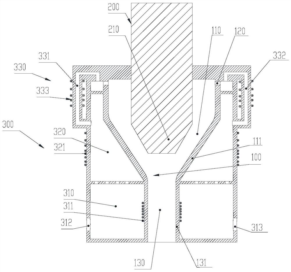
[0030] refer to figure 1 , figure 1 It is a schematic structural diagram of a plasma generator in an embodiment of the present disclosure.

[0031] In this embodiment, the plasma generator includes an anode assembly 100 , a cathode assembly 200 , a gas generation assembly 300 , a first heating...


PUM


Abstract

The invention relates to the technical field of plasma generation, and provides a plasma generator which comprises an anode assembly, a cathode assembly, a gas generation assembly and a first heating assembly. The anode assembly comprises a plasma chamber, a gas inlet and a nozzle, the gas inlet is used for introducing gas into the plasma chamber, and the nozzle is arranged at the tail end of the plasma chamber to discharge plasma outwards; the cathode assembly is provided with a discharge end, the discharge end is located in the plasma chamber, and a preset distance is formed between the discharge end and the surface of the plasma chamber; the gas generation assembly comprises a liquid chamber and a gas chamber, the liquid chamber is communicated with the gas chamber, the liquid chamber is arranged around the nozzle to be in heat conduction connection with the nozzle, and the gas chamber is communicated with the plasma chamber through the gas inlet of the anode assembly; the first heating assembly is used for heating liquid in the liquid chamber so that the liquid can be gasified and enter the air chamber, and the first heating assembly comprises an electromagnetic induction coil arranged around the nozzle.

Description

technical field [0001] The present disclosure relates to the technical field of plasma generation, in particular to a plasma generator. Background technique [0002] The plasma generator can ionize the gas through high voltage, transforming the gas into a high temperature and conductive ionized state. The plasma is conductive, which can quickly transfer the arc energy and turn it into heat energy, thereby generating a high-temperature jet. The high-temperature jets generated by the plasma generator can provide heat sources for industrial furnaces with various functions such as gasification, cracking, reaction, melting and smelting. [0003] When water vapor is used as the working gas, low-temperature and high-pressure superheated steam is generally provided through an external steam generator and a superheater, and the superheated steam is transported to the plasma generator through a steam pipeline. There will be heat loss and pressure drop when the steam is transported i...

Claims


Application Information

Patent Timeline
IPC IPC(8): H05H1/26H05H1/34
CPCH05H1/26H05H1/34
Inventor 陈培培高锐党殿杰刘军
Owner ENN SCI & TECH DEV
Learn More