Oxygenating flange and water-cooled semiconductor tail gas treatment combustion chamber
An oxygen supplement flange and tail gas treatment technology, applied in the direction of combustion method, combustion type, combustion equipment, etc., to achieve the effect of reducing explosion and avoiding interference
- Summary
- Abstract
- Description
- Claims
- Application Information
AI Technical Summary
Problems solved by technology
Method used
Image
Examples
Embodiment 1
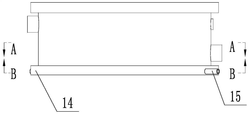
[0036] A kind of oxygen supplement flange 14, such as Figure 4 , 5As shown, the oxygen injection flange is in the form of a ring, including a radially arranged gas injection pipeline 15 and a buffer channel 16 arranged near the inner wall of the flange. The gas injection pipeline 15 injects pure oxygen into the buffer channel 16, and the inner wall of the buffer channel 16 A number of gas injection outlets 17 are arranged at equal intervals. Gas injection pipelines 15 are distributed at both ends of the oxygen supply flange 14 in the radial direction. The structure is used to transfer pure oxygen, and the pure oxygen is transferred to the buffer channel 16 collectively, and then the oxygen is uniformly transferred to the space inside the flange through the buffer channel 16 . The buffer passage 16 is annular, and the oxygen supplement flange 14 is provided with at least two gas injection pipes 15. The buffer passage 16 is provided with a number of baffles 18 corresponding t...
Embodiment 2
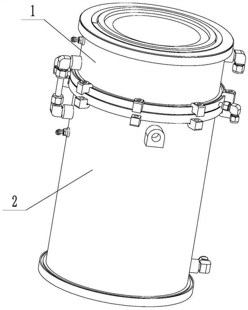
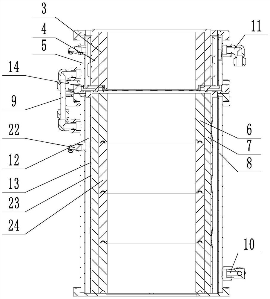
[0038] A water-cooled semiconductor exhaust gas treatment combustor, such as Figures 1 to 3 As shown, it includes an upper cavity 1 and a lower cavity 2. The upper cavity includes an upper inner cavity 3, an upper thermal insulation layer 4, and an upper water-cooling layer 5 from the inside to the outside, and the lower cavity includes the lower inner cavity 6 and the lower thermal insulation layer from the inside to the outside. Layer 7 and lower water-cooling layer 8, upper chamber 1 and lower chamber 2 are detachably connected to form an open upper container, upper water-cooling layer 5 and lower water-cooling layer 8 are connected through pipeline 9, and lower water-cooling layer 8 is provided with a water inlet 10, The upper water cooling layer 5 is provided with a water outlet 11 . Both the upper and lower inner cavities 3 & 6 are formed by stacking a number of solid ceramic plates 24 from top to bottom. The split-type composition is also used to provide a deformation...
Embodiment 3
[0044] Embodiment 2 also has the following features on the basis of Embodiment 1:
[0045] Such as Figure 5 As shown, the water cooling chamber 21 is arc-shaped, and the water inlet slots 20 are arranged near two ends of the water cooling chamber 21 . One end of the water inlet slot 20 is set at a position close to the pipeline 9 , and the other end is set at a position close to the water outlet 11 . The upper water-cooling layer 5 is provided with a partition 25, which separates the water-cooling chamber 21 from left to right, so that the water entering from the pipeline 9 needs to enter the water-cooling chamber 21 and then flow out from the water inlet slot 20 on the other side of the partition 25 Only then can it flow out from the water outlet 11. The structure avoids stagnant areas in the water-cooling layer, resulting in excessive local temperature, and the water flows through all parts of the water-cooling layer to achieve a good cooling effect.
PUM
 Abstract
Description
Claims
Application Information
 - R&D
- Intellectual Property
- Life Sciences
- Materials
- Tech Scout
- Unparalleled Data Quality
- Higher Quality Content
- 60% Fewer Hallucinations
Browse by: Latest US Patents, China's latest patents, Technical Efficacy Thesaurus, Application Domain, Technology Topic, Popular Technical Reports.
© 2025 PatSnap. All rights reserved.Legal|Privacy policy|Modern Slavery Act Transparency Statement|Sitemap|About US| Contact US: help@patsnap.com


