Nitrogen-doped carbon-loaded Mo/Pd alloy catalyst and application thereof
An alloy catalyst, nitrogen-doped carbon technology, applied in nanotechnology for materials and surface science, electrical components, battery electrodes, etc., can solve problems affecting catalyst activity and stability, and achieve high activity and simple process. Effect
- Summary
- Abstract
- Description
- Claims
- Application Information
AI Technical Summary
Problems solved by technology
Method used
Image
Examples
Embodiment 1
[0037] 105 mL of propionic acid was placed in a round-bottomed flask, a magnet was added, the rotation speed was set to 500 rpm, and the temperature was raised to 145 °C. Weigh 190 mg of pyrrole solution with an electronic balance, dissolve it in 45 mL of propionic acid, and then add it dropwise to a round-bottomed flask for about 10 min, react for 3 h, and wash with ethanol and water after the reaction to obtain a solid black powder, namely For the nano-spherical polypyrrole.
Embodiment 2-4
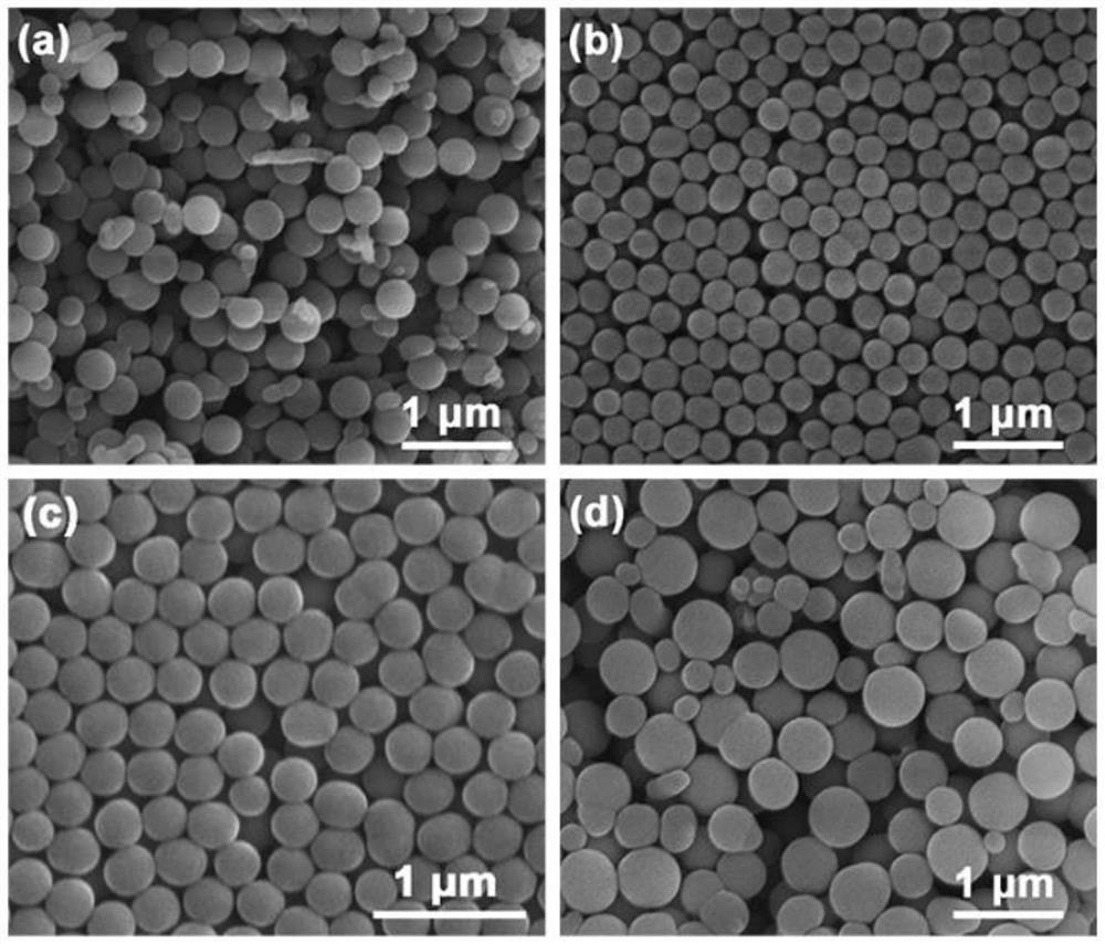
[0039] The feeding time of the pyrrole solution in Example 1 was changed to 0, 5, and 15 min, respectively, and the product morphology was obtained as follows: figure 1 shown.
[0040] The morphology of polypyrrole prepared at different feeding times was studied, such as figure 1 As shown in (a), pyrrole is directly added to propionic acid under the condition of 0 min. The polypyrrole has a spherical structure as a whole, but a small part has a non-spherical irregular shape; when the feeding time is slowed down to 5 min, likefigure 1 As shown in (b), the product is all composed of spheres, the size is relatively uniform, distributed around 250nm, and shows excellent dispersibility; when the feeding time is slowed down to 10min, as shown in Fig. figure 1 As shown in (c), the product size distribution uniformity and dispersibility are still very good, and the output is more than 2 times that of the product obtained under the condition of 5min feeding time; when the feeding time...
Embodiment 5-7
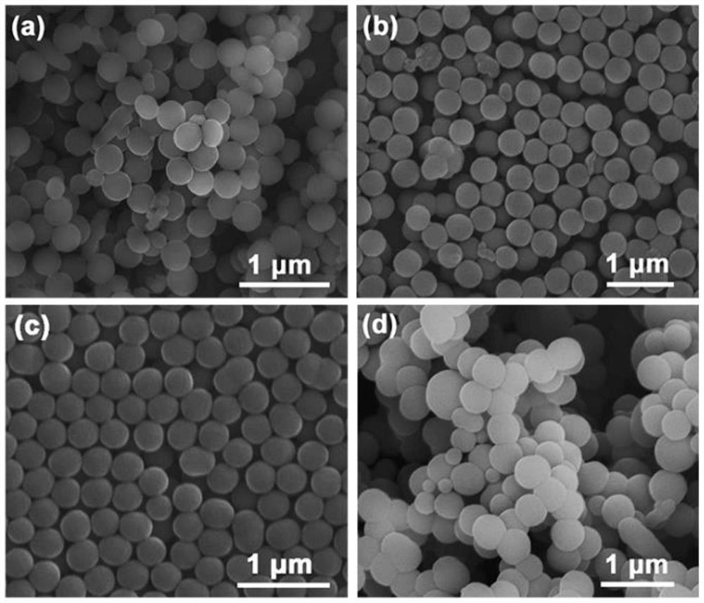
[0042] The stirring speed in Example 1 was changed to 300, 400, and 600 rpm respectively, and the product morphology was obtained as follows: figure 2 shown.
[0043] The morphology of polypyrrole prepared at different stirring speeds was studied, such as figure 2 As shown in (a), under the condition of 300 rpm, the size of the prepared polypyrrole was not uniform, and other irregular shapes appeared, but most of them kept the spherical structure; when the stirring speed was increased to 400 rpm, as shown in Fig. figure 2 As shown in (b), the spherical structure became more and more uniform, and the dispersion was also improved; when the stirring speed was increased to 500 rpm, as shown in figure 2 As shown in (c), the irregular shape completely disappeared, and the products were all polypyrrole nanospheres with narrow size distribution and good dispersibility; when the stirring speed was increased to 600 rpm, as shown in Fig. figure 2 As shown in (d), the product exhib...
PUM
| Property | Measurement | Unit |
|---|---|---|
| Limiting current density | aaaaa | aaaaa |
Abstract
Description
Claims
Application Information
 - R&D
- Intellectual Property
- Life Sciences
- Materials
- Tech Scout
- Unparalleled Data Quality
- Higher Quality Content
- 60% Fewer Hallucinations
Browse by: Latest US Patents, China's latest patents, Technical Efficacy Thesaurus, Application Domain, Technology Topic, Popular Technical Reports.
© 2025 PatSnap. All rights reserved.Legal|Privacy policy|Modern Slavery Act Transparency Statement|Sitemap|About US| Contact US: help@patsnap.com


