High-efficiency pulse load power supply and voltage hysteresis control method thereof
A technology of pulse load and hysteresis control, which is applied in the direction of control/regulation systems, electrical components, and regulation of electrical variables, etc., can solve problems such as unsatisfactory work efficiency, constant reactive power of the system, and reduced system efficiency, so as to achieve applicability Strong, reduce turn-off loss, improve work efficiency
- Summary
- Abstract
- Description
- Claims
- Application Information
AI Technical Summary
Problems solved by technology
Method used
Image
Examples
Embodiment 1
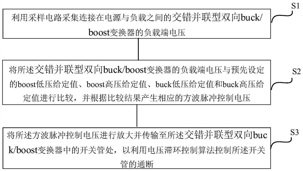
[0052] See figure 1 , figure 1 It is a flow chart of a voltage hysteresis control method for a high-efficiency pulse load power supply provided by an embodiment of the present invention. The voltage hysteresis control method includes:
[0053] S1: Use the sampling circuit to collect the load terminal voltage of the interleaved parallel bidirectional buck / boost converter connected between the power supply and the load;
[0054] S2: compare the load terminal voltage of the interleaved parallel bidirectional buck / boost converter with preset boost low voltage given value, boost high voltage given value, buck low voltage given value and buck high voltage given value, and Generate a corresponding square wave pulse control voltage according to the comparison result;
[0055] S3: amplify the square wave pulse control voltage and transmit it to the switching tube in the interleaved parallel bidirectional buck / boost converter, so as to control the switching of the switching tube by u...
Embodiment 2
[0070] On the basis of the above embodiments, this embodiment provides a high-efficiency pulse load power supply. See Figure 4 , Figure 4 It is a block diagram of a high-efficiency pulse load power supply provided by the embodiment of the present invention. The intermittent new energy power supply system includes an interleaved parallel bidirectional buck / boost converter 1, a drive circuit 2, a sampling circuit 3 and a control circuit 4, wherein the interleaved parallel bidirectional buck / boost converter 1 is connected between a power source 5 and a load 6 between the power source 5 and the load 6 for voltage conversion and energy bidirectional transmission; the sampling circuit 3 is connected to one end of the interleaved parallel bidirectional buck / boost converter 1 close to the load 6 for collecting the interleaved parallel bidirectional buck The load terminal voltage of / boost converter 1; the control circuit 4 is connected to the sampling circuit 3, and is used to com...
PUM
 Abstract
Description
Claims
Application Information
 - R&D
- Intellectual Property
- Life Sciences
- Materials
- Tech Scout
- Unparalleled Data Quality
- Higher Quality Content
- 60% Fewer Hallucinations
Browse by: Latest US Patents, China's latest patents, Technical Efficacy Thesaurus, Application Domain, Technology Topic, Popular Technical Reports.
© 2025 PatSnap. All rights reserved.Legal|Privacy policy|Modern Slavery Act Transparency Statement|Sitemap|About US| Contact US: help@patsnap.com


