Piezoelectric resonator and manufacturing method thereof

A piezoelectric resonator and piezoelectric layer technology, applied in the field of piezoelectricity, can solve the problems of acoustic energy loss, associated lateral clutter leakage, increased filter band ripple and insertion loss, etc.

Pending Publication Date: 2021-12-31
AAC ACOUSTIC TECH (SHENZHEN) CO LTD
View PDF0 Cites 2 Cited by
  • Summary
  • Abstract
  • Description
  • Claims
  • Application Information

AI Technical Summary

Problems solved by technology

[0005] In the prior art, in principle, although the main mode at resonance is the longitudinal wave mode, there will still be some spurious modes formed with the longitudinal wave excitation
These parasitic modes can be standing waves, which form spurious peaks on the electrical characteristic curve of the device, increasing the in-band ripple and insertion loss of the filter; they can also be laterally propagating clutter, causing energy leakage and increasing the insertion loss of the filter , reduce the quality factor (Q value) of the device
[0006] Starting from the typical resonator structure, the deficiencies of the prior art are as follows: 1. In the area where the top electrode is led out, the part where the piezoelectric layer transitions from the bottom electrode to the outside of the bottom electrode is more likely to generate defect areas during the formation process, resulting in acoustic energy The loss and Q value are reduced; 2. Since the connection between the top electrode and the top electrode lead-out structure is usually a left-right (horizontal) structure, part of the associated lateral clutter will still leak out of the resonance area through the bridge / electrode lead-out part; 3. Due to The top electrode and the bottom electrode may also have overlapping areas outside the cavity, which increases the area of ​​the non-resonant area, which is equivalent to connecting parasitic capacitance in parallel, reducing the effective electromechanical coupling coefficient; on the other hand, due to the increase in the area of ​​the non-resonant area, the acoustic The loss increases, resulting in a decrease in the Q value; 4. In the prior art, the bottom electrode may be shortened to the inside of the cavity, but the defect region generated by the piezoelectric layer in the transition region is close to the end of the resonance region, and these defect regions will still cause energy in practical applications. loss, and the shortening of the bottom electrode leads to a reduction in the area of ​​the resonance region, the effective electromechanical coupling coefficient keff^2 will still be reduced, and the contact area between the bottom electrode and the substrate will also be reduced, resulting in a decrease in the heat dissipation capability and structural strength of the device
5. When constructing the bridge structure of piezoelectric resonators in the related art, sacrificial layers or low acoustic impedance materials are often deposited on the piezoelectric layer first, and then patterned, and then the top electrode is deposited. During this process, the resonant The surface of the piezoelectric layer in the region will be exposed to various solutions and high-energy plasma, the surface defects will increase, the roughness will increase, and the surface quality will decrease, resulting in an increase in energy loss and a decrease in the Q value of the piezoelectric resonator during operation.

Method used


Image

  • Piezoelectric resonator and manufacturing method thereof
  • Piezoelectric resonator and manufacturing method thereof
  • Piezoelectric resonator and manufacturing method thereof

Examples


Embodiment 1

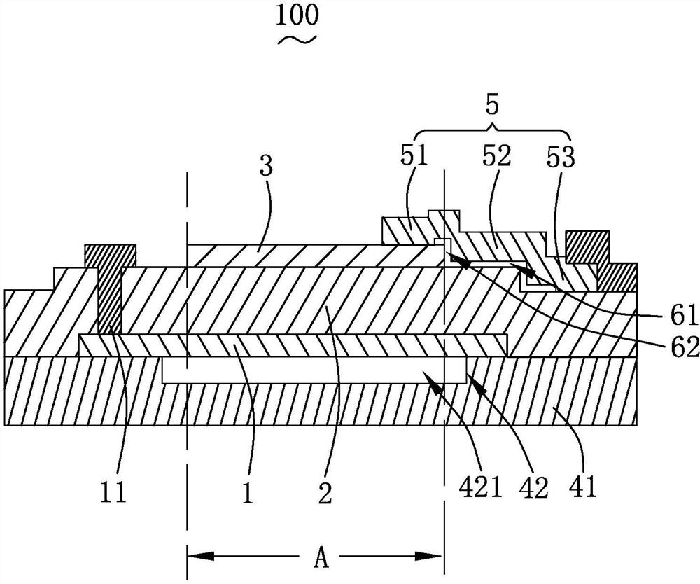
[0052] see figure 1 , is a structural schematic diagram of Embodiment 1 of the piezoelectric resonator of the present invention. The present invention provides a piezoelectric resonator 100 , comprising: a bottom electrode 1 , a piezoelectric layer 2 , a top electrode 3 , an acoustic wave reflection layer structure 42 , and a top electrode lead-out structure 5 .

[0053] The piezoelectric layer 2 is stacked on the bottom electrode 1 .

[0054] The top electrode 3 is stacked on a side of the piezoelectric layer 2 away from the bottom electrode 1 .

[0055] The acoustic wave reflection layer structure 42 is formed on a side of the bottom electrode 1 away from the piezoelectric layer 2 . That is, the acoustic wave reflection layer structure 42 is formed under the top electrode 3 , the piezoelectric layer 2 and the bottom electrode 1 .

[0056] The top electrode lead-out structure 5 is located on the side of the piezoelectric layer 2 away from the bottom electrode 1 .

[0057]...

Embodiment approach 2

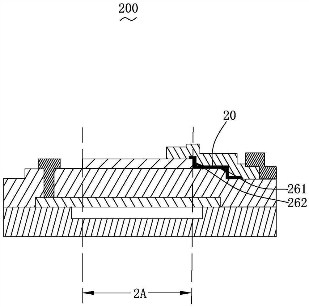
[0069] The present invention also provides another implementation mode, please combine figure 2 Shown is a schematic structural diagram of Embodiment 2 of the piezoelectric resonator of the present invention. The structure of the piezoelectric resonator 200 is basically the same as that of the first embodiment above, except that:

[0070] The second air gap 262 is filled with a functional material 20, which can isolate the bridge structure from the top electrode, realize the reflection of sound waves, reflect the sound wave energy back to the resonance area, and prevent part of the transverse clutter from passing through the The region leaks out of the resonance region 2A, thereby improving the Q value of the piezoelectric resonator 200 .

[0071] The first air gap 261 is filled with functional materials 20, which can reduce the area of ​​the non-resonant region and reduce the problem of reducing the effective electromechanical coupling coefficient caused by parasitic capaci...

Embodiment 3

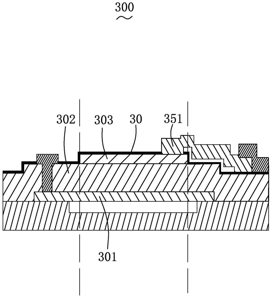
[0075] The present invention also provides another implementation mode, please combine image 3 Shown is a schematic structural diagram of Embodiment 3 of the piezoelectric resonator of the present invention. The structure of the piezoelectric resonator 300 is basically the same as that of the first embodiment above, except that:

[0076] The piezoelectric resonator 300 further includes a passivation layer 30 . The passivation layer 30 is stacked on a side of the top electrode 303 away from the piezoelectric layer 302 and at least partially covers the top electrode 303 . Of course, the electrode connection end 351 needs to penetrate the passivation layer 30 and be connected to the top electrode 303 .

[0077] However, the arrangement of the purification layer 30 can effectively protect the top electrode 303 and the piezoelectric layer 302 and improve structural reliability.

[0078] Except for the above differences, its structure is the same as that of Embodiment 1, and the ...


PUM


Abstract

The invention provides a piezoelectric resonator. The piezoelectric resonator comprises a bottom electrode; a piezoelectric layer is stacked on the bottom electrode; a top electrode is stacked on the side, away from the bottom electrode, of the piezoelectric layer; a sound wave reflecting layer structure is formed on the side, away from the piezoelectric layer, of the bottom electrode; a top electrode leading-out structure is positioned on one side, far away from the bottom electrode, of the piezoelectric layer; the bottom electrode, the piezoelectric layer, the top electrode and the sound wave reflecting layer structure are overlapped together to form a space region which is defined as a resonance region; the top electrode leading-out structure is connected with the top electrode in the resonance area and extends out of the resonance area from the inside of the resonance area, and the top electrode leading-out structure and the orthographic projection part of the top electrode towards the piezoelectric layer are overlapped. The invention further provides a manufacturing method of the piezoelectric resonator. Compared with the prior art, the manufacturing method of the piezoelectric resonator can reduce the influence of the growth defect of the piezoelectric layer on the performance of the device, so that the piezoelectric resonator structure has a higher quality factor Q and a higher effective electromechanical coupling coefficient.

Description

【Technical field】 [0001] The invention relates to the field of piezoelectric technology, in particular to a piezoelectric resonator and a manufacturing method thereof. 【Background technique】 [0002] With the increasing number of smart devices and the continuous popularization of Internet of Things and 5G technologies, the demand for high-performance filters and multiplexers is increasing. As an important part of filters and multiplexers, acoustic resonators have been the focus of research in recent years. The current mainstream acoustic resonance technology includes surface acoustic wave technology SAW (Surface Acoustic Wave) and bulk acoustic wave technology BAW (Bulk Acoustic Wave). Due to the simple manufacturing process and low cost, the resonator using SAW technology occupies the mainstream market of medium and low frequency (below 2GHz). The disadvantages of SAW resonators are low quality factor value, poor temperature drift of materials and poor compatibility with ...

Claims


Application Information

Patent Timeline
Patent Type & Authority Applications(China)
IPC IPC(8): H03H9/02H03H3/02H03H3/08
CPCH03H9/02015H03H9/02086H03H9/02543H03H9/02818H03H3/02H03H3/08
Inventor 吴珂吕丽英杨帅王超庄智强张丽蓉吴一雷
Owner AAC ACOUSTIC TECH (SHENZHEN) CO LTD
Why Eureka
Try Eureka