
Metasurface-based optical fiber humidity sensor and manufacturing method thereof,

A technology of humidity sensor and fiber optic sensor, which is applied in instruments, scientific instruments, and material analysis through optical means, and can solve problems such as small effective sensing area, limited number of effective resonance peaks, and large effective sensing volume

Active Publication Date: 2022-01-04
BEIJING INSTITUTE OF TECHNOLOGYGY
View PDF8 Cites 1 Cited by
  • Summary
  • Abstract
  • Description
  • Claims
  • Application Information

AI Technical Summary

Problems solved by technology

However, most fiber optic humidity sensors are coated with humidity-sensitizing materials on the side of the fiber, or humidity-sensitive materials are used as filling materials for the resonant cavity, and their effective sensing volume is large, which becomes an obstacle to the further miniaturization of fiber optic humidity sensors.
In addition, the limited number of measured sensing parameters due to cross-sensitivity has been plagued by fiber optic sensors
Multi-peak technology is an effective method to solve cross-sensitivity, but the existing fiber optic sensor has a limited number of effective resonance peaks, so there is an urgent need for a fiber optic humidity sensor with a small effective sensing area and multiple resonance peaks

Method used

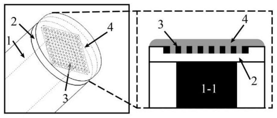
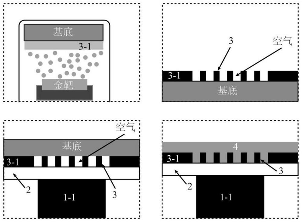
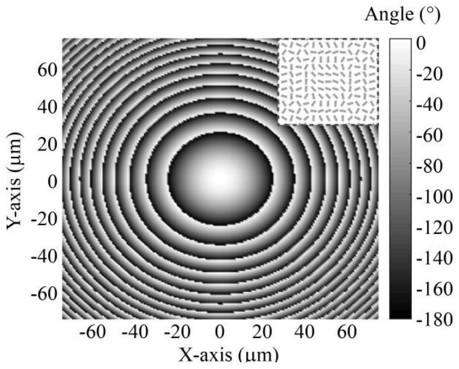

Image

  • Metasurface-based optical fiber humidity sensor and manufacturing method thereof,
  • Metasurface-based optical fiber humidity sensor and manufacturing method thereof,
  • Metasurface-based optical fiber humidity sensor and manufacturing method thereof,

Examples


Embodiment Construction

[0035] The present invention will be described in detail below with reference to the drawings and embodiments. At the same time, the technical problems and beneficial effects solved by the technical solution of the present invention are also described. It should be pointed out that the described embodiments are only intended to facilitate the understanding of the present invention, and have no limiting effect on it.

[0036] Such as figure 2 As shown, the preparation method of the optical fiber humidity sensor based on the fiber end metasurface disclosed in this embodiment, the specific implementation method is as follows:

[0037] Step 1: Clean the substrate first, and use a coating machine to prepare a metal film 3-1 on one side of the substrate. Usually, thermal resistance evaporation coating, electron beam evaporation coating, ion beam evaporation coating, magnetic sputtering coating, etc. can be used.

[0038] In order to ensure easy peeling between the metal film 3-1 a...


PUM

PropertyMeasurementUnit
thicknessaaaaaaaaaa
thicknessaaaaaaaaaa

Abstract

The invention discloses a metasurface-based optical fiber humidity sensor and a manufacturing method thereof and belongs to the technical field of sensing and measurement application. The optical fiber sensor disclosed by the invention is mainly composed of an optical fiber, an adhesive, a metasurface and a sensitizing substance. The end face of the optical fiber and the metasurface are fixed together through the adhesive; the sensitizing substance coats the metasurface; and the metasurface is composed of nanopore arrays which have rectangular cross sections and have different sizes and different azimuth angles. According to the optical fiber sensor, a plurality of harmonic peaks with different refractive index sensitivities are generated by adopting metal micro-nano structures with different rotation angles, and measurement of a plurality of sensing parameters can be realized by monitoring changes of characteristic parameters of the harmonic peaks. According to the manufacturing method, the manufacturing cost and the manufacturing period of the fiber end optical fiber sensor can be reduced. The sensor has the advantages of small effective sensing area, multiple harmonic peaks and high robustness, and is applied to the fields of industry, agriculture, medical treatment, chemical biology and the like.

Description

technical field [0001] The invention relates to an optical fiber humidity sensor based on a metasurface and a manufacturing method thereof, belonging to the field of humidity sensors. Background technique [0002] Continuous electrochemical damage caused by changes in external humidity conditions is an important reason for the deterioration of the structural reliability of large buildings. It is of great significance to continuously monitor the external humidity environment and make timely repairs before its performance deteriorates. Therefore, there is an urgent need for a real-time humidity monitoring tool that is small in size and does not affect the mechanical properties of the metal structure itself. [0003] Fiber optic sensors have many advantages such as durability, anti-electromagnetic interference and corrosion resistance, small size, and fast response, which are very suitable for in-situ measurement. In recent years, researchers have proposed a variety of optica...

Claims


Application Information

Patent Timeline
Patent Type & Authority Applications(China)
IPC IPC(8): G01N21/41G01N21/552F16B11/00
CPCG01N21/41G01N21/553F16B11/00Y02A90/10
Inventor 黄玲玲刘银王涌天李晓炜
Owner BEIJING INSTITUTE OF TECHNOLOGYGY
Learn More