Manufacturing method and system of integrated antenna-containing shell

A manufacturing method and antenna shell technology, applied to antennas, manufacturing tools, antenna supports/mounting devices suitable for movable objects, etc., can solve problems such as high process costs, increased product costs, and defective products, and achieve improvement Production efficiency and yield rate, reduction of spraying cost, effect of height difference improvement

Active Publication Date: 2022-01-04
SHENZHEN CICENT COMM TECH CO LTD
View PDF6 Cites 2 Cited by
  • Summary
  • Abstract
  • Description
  • Claims
  • Application Information

AI Technical Summary

Problems solved by technology

The process cost of this method is high and the yield rate is low, because the antenna has an obvious height difference (about 20um) on the surface of the plastic part of the shell, and the product needs to be removed from the spraying fixture during the spraying process, and then the sprayed product is polished. Then assemble the product with a spraying fixture, and then spray it. This process needs to be repeated several times. For the spraying process, the spraying automatic line requires a lot of labor to disassemble and assemble the product in batches. At the same time, the grinding process after spraying is easy to cause damage to the product. Bad, this process greatly increases the product cost, and the good product rate is low. The general spraying good product rate in the industry is 75% or below, and the products lost in the spraying process are antenna semi-finished products that have included laser coating electrical performance testing and other links. The cost is high and the product is not good. rate is also high

Method used


Image

  • Manufacturing method and system of integrated antenna-containing shell
  • Manufacturing method and system of integrated antenna-containing shell
  • Manufacturing method and system of integrated antenna-containing shell

Examples


Embodiment Construction

[0057] The preferred embodiments of the present invention will be further described in detail below in conjunction with the accompanying drawings.

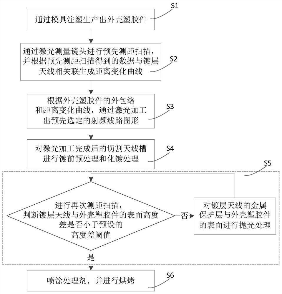
[0058] Such as figure 1 with figure 2 As shown, this example provides a manufacturing method for an integrated antenna housing, including the following steps:

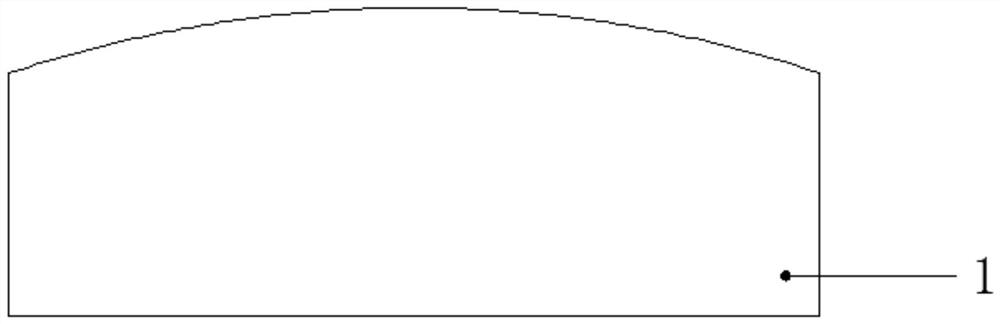
[0059] Step S1, producing the shell plastic part 1 through mold injection;

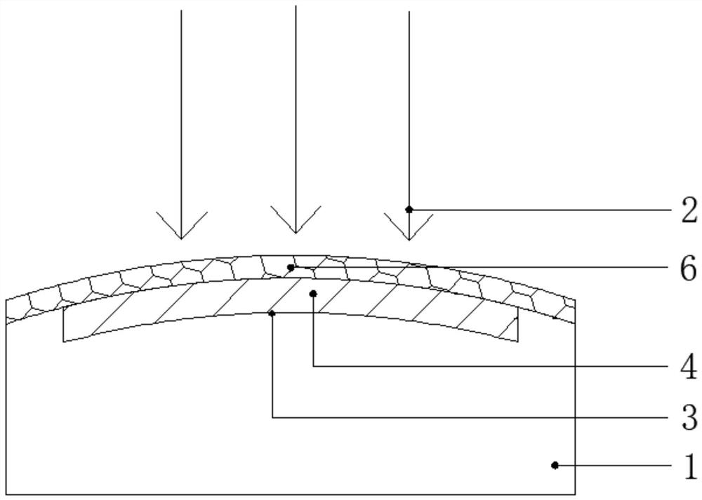
[0060] Step S2, performing a pre-ranging scan through the laser measuring lens 10, emitting a ranging laser 5, and correlating the data obtained by the pre-ranging scan with the coating antenna to generate a distance change curve;

[0061] Step S3, according to the outer envelope and distance change curve of the shell plastic part 1, process the pre-selected radio frequency circuit pattern 3 by laser, that is, emit the cutting laser 2 through the laser cutting lens 11, and in the process of laser processing, pass the laser The measurement lens 10 performs a second distance measurement scan, an...


PUM


Abstract

The invention provides a manufacturing method and system for an integrated antenna-containing shell. The manufacturing method comprises the steps that S1, producing a shell plastic part; S2, carrying out pre-ranging scanning through a laser measuring lens, and generating a distance change curve; S3, processing a preselected radio frequency circuit pattern through laser according to the outer envelope of the shell plastic part and the distance change curve; S4, carrying out pre-plating pretreatment and chemical plating treatment on an antenna groove; S5, carrying out distance measurement scanning again until the surface height difference between the coating antenna and the shell plastic part is lower than a preset height difference threshold value; and S6, srapying a treating agent, and carrying out baking. The method and system can adapt to outer enveloping of the shell plastic part, the height difference between the coating antenna and the shell plastic part is greatly improved, repeated dismounting, mounting and polishing of the coating clamp for a product are not needed, the machining technology is greatly simplified, the production cost is effectively reduced, and the production efficiency and the yield are improved.

Description

technical field [0001] The present invention relates to a coating antenna processing method, in particular to a manufacturing method for an integrated antenna housing, and further relates to an integrated antenna housing manufacturing system using the manufacturing method for an integrated antenna housing. Background technique [0002] With the development and update of information technology, mobile communication technology has developed rapidly, especially the volume and weight of mobile terminals have also been reduced a lot, which also promotes the rapid development of antennas for mobile terminals. For antennas on the shell of mobile terminal products Generally speaking, the method of laser processing coating is widely used now, mainly including the following types. [0003] In the first way, when the laser-processed plated antenna is fabricated on the outer surface of the electronic product casing, the plastic parts of the casing are over-molded to achieve the surface ...

Claims


Application Information

Patent Timeline
Patent Type & Authority Applications(China)
IPC IPC(8): H01Q1/38H01Q1/22H01Q1/27B29D99/00B23K26/38B23K26/402B23K26/70B23K26/03B23K26/08
CPCH01Q1/38H01Q1/22H01Q1/27B29D99/006B23K26/38B23K26/402B23K26/702B23K26/032B23K26/0823
Inventor 肖成博李军
Owner SHENZHEN CICENT COMM TECH CO LTD
Why Eureka
Try Eureka