Millimeter wave frequency band rectangular horn antenna substructure and N-element antenna array

A millimeter-wave frequency band and horn antenna technology, which is applied to antenna arrays, waveguide horns, antennas, etc., can solve problems such as difficult engineering implementation, difficulty in manufacturing unit horns, and small size of millimeter-wave frequency band antennas to achieve good manufacturability and structure Compact and guaranteed electromagnetic performance

Active Publication Date: 2022-01-07
SOUTHWEST CHINA RES INST OF ELECTRONICS EQUIP
View PDF10 Cites 0 Cited by
  • Summary
  • Abstract
  • Description
  • Claims
  • Application Information

AI Technical Summary

Problems solved by technology

[0004] The millimeter-wave frequency band antenna is relatively small in size. For some compact millimeter-wave frequency band rectangular horn antenna arrays, in order to suppress the generation of antenna grid lobes and ensure the electromagnetic performance indicators of the antenna array, the unit spacing L is only a little larger than the unit horn mouth width W. , in the limit case, it is only 0.2mm larger. If the structural design is carried out according to the above method, first disassembled into unit horns and then assembled into an array. Very difficult, difficult to achieve in engineering

Method used


Image

  • Millimeter wave frequency band rectangular horn antenna substructure and N-element antenna array
  • Millimeter wave frequency band rectangular horn antenna substructure and N-element antenna array
  • Millimeter wave frequency band rectangular horn antenna substructure and N-element antenna array

Examples


Embodiment 1

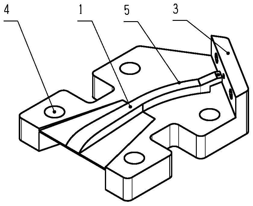
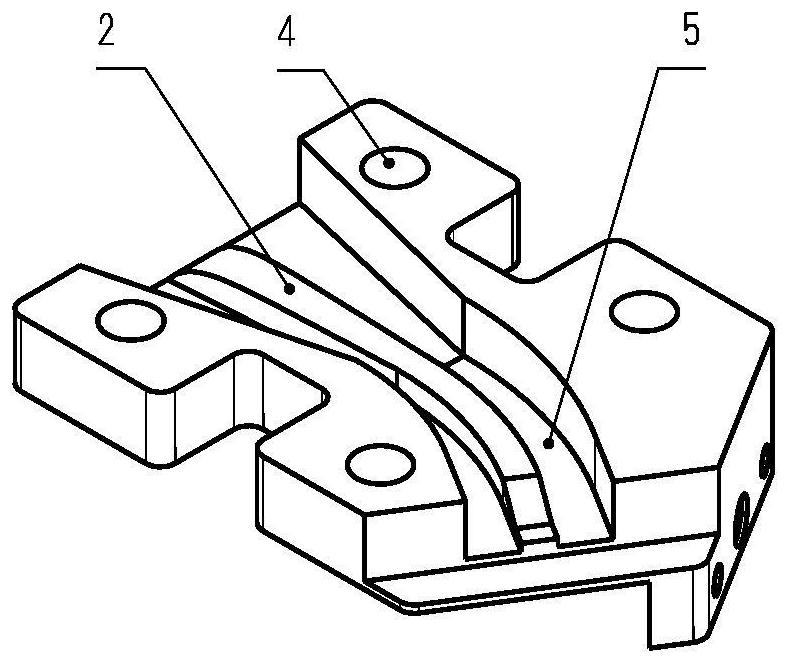
[0029] Such as figure 2 , image 3 As shown, this embodiment proposes a rectangular horn antenna substructure in the millimeter wave frequency band, including a main structure. The bottom of the main structure is V-shaped. The cover side 1 is provided with a straight waveguide section 5 and a rear cover 3, and the rear cover 3 is installed on any side of the V shape of the main structure. The straight waveguide section 5 extends from the top of the ridge cover side 1 to the rear cover 3, and is located The end of the straight waveguide section 5 at the cover plate 3 is provided with a blind hole 7, and the rear cover plate 3 is provided with a through hole 6, which corresponds to the position of the blind hole 7; The straight waveguide section 5 of the spine box side 2 extends from the top of the spine box side 2 to the V-shaped side of the bottom of the main structure without the back cover 3 .

[0030] Specifically, the straight waveguide section on the spine cover side 1...

Embodiment 2

[0035] Such as Figure 5 , Figure 6 , Figure 7As shown, this embodiment proposes a 7-element antenna array, which is implemented based on the millimeter-wave frequency band rectangular horn antenna substructure of Embodiment 1. Specifically, the 7-element antenna array includes: 3 rear covers arranged on the main structure The first substructure 9 on one side of the V shape, the second substructure 8, the ridge cover 10, the ridge box 11 and 7 pieces of antenna electrical connectors 12 are arranged on the other side of the V shape of the main structure with three rear cover plates, The ridge cover side of the first substructure 9 is attached to the spine box side of the second substructure 8, and the three first substructures 9 and the three second substructures 8 are installed alternately. The inner side of the ridge cover 10 There is a straight waveguide section and a rear cover plate corresponding to the spine box side of the first substructure 9, and the inner side of ...


PUM


Abstract

The invention provides a millimeter wave frequency band rectangular horn antenna substructure and an N-element antenna array. The substructure comprises a main body structure, the bottom end of the main body structure is V-shaped, the two sides of the main body structure are respectively a ridge cover side and a ridge box side, the ridge cover side is provided with a straight waveguide section and a rear cover plate, the rear cover plate is installed on any side of the V-shaped main body structure, the straight waveguide section extends to the rear cover plate from the side top end of the ridge cover, a blind hole is formed in the tail end of the straight waveguide section located at the rear cover plate, a through hole is formed in the rear cover plate, and the through hole corresponds to the blind hole in position; the ridge box side comprises a groove and a straight waveguide section arranged in the groove, and the straight waveguide section of the ridge box side extends from the top end of the ridge box side to the side, without the rear cover plate, of the V shape at the bottom end of the main body structure. According to the scheme, the wall thickness of the horn mouth part is kept to the maximum extent, the manufacturing difficulty of the horn mouth part is effectively reduced, the horn mouth part is particularly suitable for structural design and manufacturing of a small-size and high-precision rectangular horn antenna array of a millimeter wave frequency band, and arraying of any number of unit antennas can be achieved.

Description

technical field [0001] The invention relates to the field of antenna structures, in particular to a rectangular horn antenna substructure in the millimeter wave frequency band and an N-element antenna array. Background technique [0002] The invention relates to a rectangular horn antenna array in the millimeter wave frequency band, which has the advantages of wide operating frequency band, large power capacity, good radiation characteristics, strong anti-interference performance, small size and easy integration, and is currently widely used in communication, radar, electronic warfare and other fields. In the existing literature, there are many researches on the electromagnetic design of this antenna array, but the introduction to its structure is only a schematic diagram, lacking a detailed introduction to the structure design. As we all know, the antenna is a typical mechatronic product, the selection of the structure form and the detailed structural design of each compone...

Claims


Application Information

Patent Timeline
Patent Type & Authority Applications(China)
IPC IPC(8): H01Q21/00H01Q13/06H01Q1/12H01Q13/02
CPCH01Q21/00H01Q13/06H01Q1/12H01Q13/02Y02D30/70
Inventor 张登材罗旭谭继勇况泽灵王森黄福清陈以金张义萍刘颖古智祥李培
Owner SOUTHWEST CHINA RES INST OF ELECTRONICS EQUIP
Why Eureka
Try Eureka