Light skid-mounted urea pyrolysis pneumatic SCR tail gas treatment system and method and application

A technology for tail gas treatment and pyrolysis gas, which is applied in separation methods, chemical instruments and methods, and dispersed particle separation. The effect of small area, small amount of installation work and easy operation

Pending Publication Date: 2022-01-11
AEROSPACE ENVIRONMENTAL ENG
View PDF2 Cites 0 Cited by
  • Summary
  • Abstract
  • Description
  • Claims
  • Application Information

AI Technical Summary

Problems solved by technology

[0004] 1. Diesel engine flue gas selective catalytic reduction denitrification device (CN204247073U) has announced a kind of diesel engine flue gas selective catalytic reduction denitrification device, but the reducing agent of this equipment is mixed with the tail gas in the flue, and the mixing distance is longer. Moreover, the SCR reactor adopts a horizontal layout, the flow field is uneven, the utilization efficiency of the catalyst is not high, the overall floor area is large, it is not easy to install and maintain, and the denitrification efficiency is low
[0005] 2. A diesel generator tail gas denitrification process device (CN204371461U) discloses a diesel generator tail gas denitrification process device, which also adopts SCR technology, and its reducing agent and tail gas are mixed with the SCR reactor, and the reactor is Horizontal type, resulting in long mixing distance, poor mixing effect, uneven flow field, low catalyst utilization rate, and larger floor area, which is not only not conducive to installation and maintenance, but also affects the overall denitrification effect

Method used


Image

  • Light skid-mounted urea pyrolysis pneumatic SCR tail gas treatment system and method and application
  • Light skid-mounted urea pyrolysis pneumatic SCR tail gas treatment system and method and application
  • Light skid-mounted urea pyrolysis pneumatic SCR tail gas treatment system and method and application

Examples


Embodiment Construction

[0036] The present invention will be described in further detail below in conjunction with specific examples. The following examples are only descriptive, not restrictive, and cannot limit the protection scope of the present invention.

[0037] The raw materials used in the present invention, if no special instructions, are conventional commercially available products, the methods used in the present invention, if no special instructions, are conventional methods in this area, and the quality of each material used in the present invention is routine use quality. Structures, connections, etc. that are not described in detail in the present invention can be understood as conventional technical means in the art.

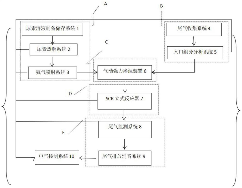
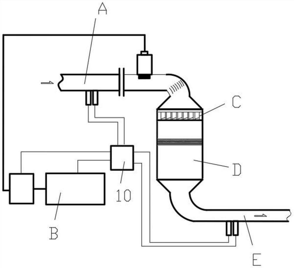
[0038] A light skid-mounted urea pyrolysis pneumatic SCR tail gas treatment system, such as figure 1 , figure 2As shown, the treatment system includes a reducing agent preparation system A, an exhaust gas component analysis system B, a pneumatic intensive blending sy...


PUM


Abstract

The invention discloses a light skid-mounted urea pyrolysis pneumatic SCR tail gas treatment system, which comprises a reducing agent preparation system, a tail gas component analysis system, a pneumatic powerful mixing system, an SCR reaction system and a tail gas emission system; the input end of the pneumatic powerful mixing system is connected with the output end of the reducing agent preparation system and the output end of the tail gas component analysis system, the input end of the tail gas component analysis system can input equipment tail gas, and the output end of the pneumatic powerful mixing system is connected with the input end of the SCR reaction system; the output end of the SCR reaction system is connected with the input end of the tail gas emission system, and the output end of the tail gas emission system can discharge the tail gas which is subjected to denitration treatment and is qualified. The treatment system adopts urea to prepare reducing agent ammonia gas, wherein the safety is high, the economical efficiency is strong, tail gas and ammonia gas can be fully mixed through the pneumatic powerful mixing device, the mixing distance is short, the mixed tail gas flow field is uniform, the denitration efficiency is improved, ammonia escape is reduced, and the operation is simple and convenient.

Description

technical field [0001] The invention belongs to the technical field of tail gas post-treatment of industrial equipment, in particular to a light skid-mounted urea pyrolysis pneumatic SCR tail gas treatment system, method and application. Background technique [0002] On September 10, 2013, my country issued the "Action Plan for Air Pollution Prevention and Control" (2013.9.10). It mentions accelerating the construction of desulfurization, denitrification, and dust removal renovation projects in key industries. Strictly implement the total amount control of pollutant discharge, and make whether the discharge of sulfur dioxide, nitrogen oxides, smoke dust and volatile organic compounds meet the total amount control requirements as a precondition for the environmental and impact assessment and approval of construction projects. This provides policy support for the tail gas denitrification market of small and medium-sized equipment, and puts forward technical guidance and norma...

Claims


Application Information

Patent Timeline
Patent Type & Authority Applications(China)
IPC IPC(8): B01D53/86B01D53/56
CPCB01D53/8631B01D2251/2062
Inventor 王弘坤黄虎成王冬冬王宏伟孟庆鹏
Owner AEROSPACE ENVIRONMENTAL ENG
Why Eureka
Try Eureka