Ruthenium-based sputtering target and method for manufacturing same

A sputtering target and sputtering technology, used in sputtering coating, vacuum evaporation coating, ion implantation coating, etc. It is easy to produce particles and other problems, so as to achieve the effect of low anisotropy of the structure, low particle size and high film thickness uniformity

Pending Publication Date: 2022-01-11
FURUYA KINZOKU KK
View PDF6 Cites 0 Cited by
  • Summary
  • Abstract
  • Description
  • Claims
  • Application Information

AI Technical Summary

Problems solved by technology

However, in general, gas components remain in the voids of the sintered body, and this gas is introduced during welding to cause welding defects, so particles are likely to be generated, so it is not preferable.
In addition, the metal structure of the sintered body of the base material and the welded part are greatly different, so it is considered that the film thickness uniformity and surface uniformity of the sputtered film are deteriorated due to the difference in the sputtering rate.

Method used


Image

  • Ruthenium-based sputtering target and method for manufacturing same
  • Ruthenium-based sputtering target and method for manufacturing same
  • Ruthenium-based sputtering target and method for manufacturing same

Examples


Embodiment 1

[0082] A seed plate of random anisotropic crystals containing a hexagonal close-packed structure of ruthenium metal was prepared. Separately, a ruthenium raw material was prepared. The ruthenium powder (purity is 99.99 mass %) in 5 × 10 -2 After melting in a vacuum environment below Pa, it is solidified to obtain a ruthenium ingot. A ruthenium ingot was pulverized to obtain a pulverized product, which was used as a ruthenium raw material. The raw material of ruthenium is cast ruthenium sheet. Arrange the pulverized material as the ruthenium raw material on the seed plate in a flat shape, at 5×10 -2Each fragment was heated from above in a vacuum environment below Pa to melt it, and then cooled to produce a ruthenium plate having a seed plate in the lower part. Then, the cast ruthenium sheets are arranged flat on the ruthenium plate with the seed plate at the bottom, at 5×10 -2 Each fragment was heated from above in a vacuum environment below Pa to melt it, and then cooled ...

reference example 1

[0088] Ruthenium powder (purity: 99.99% by mass) was used as a reference example.

[0089] (X-ray diffraction)

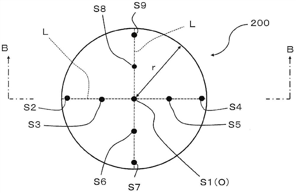
[0090] According to (condition 2), X-ray diffraction (CuKα) was measured about the square plate-shaped Ru sputtering target material of Example 1, Comparative Example 1, and Comparative Example 2, respectively. Regarding Example 1, in Table 1 and Table 2, relative integrated intensities of crystal planes and peaks are summarized for the main peak, the second peak, the third peak, and the fourth peak. P1~P9 in Table 1 and Figure 5 corresponding to P1~P9. In addition, D1~D9 in Table 2 and Image 6 corresponding to D1~D9. Regarding Comparative Example 1, regarding Figure 5 P1~P9 of Image 6 For the main peak, the second peak, the third peak and the fourth peak generated at the measurement sites of D1 to D9, the relative integrated intensity between the crystal plane and the peak does not change, so it is shown in Table 3 Figure 5 P1 and Image 6 The results ...


PUM

PropertyMeasurementUnit
melting pointaaaaaaaaaa

Abstract

The purpose of the present disclosure is to provide: a Ru-based sputtering target which has no void, high purity and a low level of structural anisotropy and which makes it possible to form a Ru-based film having low particle count, high film thickness uniformity and high two-dimensional uniformity; and a method for manufacturing the Ru-based sputtering target. The ruthenium-based sputtering target of the present disclosure has a cast structure, wherein a sputter surface of the sputtering target has at least two regions, and crystal surfaces in the regions each of which is specified by a main peak of X-ray diffraction are different from each other.

Description

technical field [0001] The present invention relates to a kind of ruthenium (Ru) system sputtering target material and its manufacturing method, used for forming the MRAM (MagnetoresistiveRandom Access Memory, random access memory) as non-volatile RAM (Random Access Memory, random access memory) being developed in recent years Ru thin film used in electrodes such as magnetoresistive random access memory). Background technique [0002] The thickness of the Ru thin film used in MRAM is extremely thin, only a few nanometers. If particles as impurities adhere to the surface of the film, the yield of the product will be greatly reduced. Therefore, it is expected that this particle will be infinitely close to zero in component fabrication. [0003] In addition, it is considered that the diameter of the wafer tends to increase in diameter, and a wafer of φ300 mm is now the standard. Furthermore, it is required to uniformly apply a nanoscale film on the surface of the wafer having...

Claims


Application Information

Patent Timeline
Patent Type & Authority Applications(China)
IPC IPC(8): C23C14/34
CPCH01J37/3426C23C14/3414C23C14/14C23C14/3407H01J37/3491H01J37/3423H01J2237/332
Inventor 丸子智弘荒川等大友将平鈴木雄
Owner FURUYA KINZOKU KK
Why Eureka
Try Eureka