Eureka AIR delivers breakthrough ideas for toughest innovation challenges, trusted by R&D personnel around the world.

Air pressure adjusting mechanism for detecting pressure in body cavity, detection catheter and detection device

A technology of air pressure adjustment and body cavity, which is applied in catheters, therapeutic feeding tubes, applications, etc., can solve the problems of increasing the load of medical staff, inaccurate quantification, and reduced detection efficiency, so as to avoid layout methods, improve efficiency and accuracy, Effects of a quick stress test

Active Publication Date: 2022-01-18
GUANGZHOU NAT LAB +1
View PDF7 Cites 0 Cited by
  • Summary
  • Abstract
  • Description
  • Claims
  • Application Information

AI Technical Summary

Problems solved by technology

[0004] At present, when detecting the patient's gastric pressure or esophageal pressure in the prior art, medical personnel need to connect the syringe to the interface of the detection catheter, inject gas into the balloon through the syringe to detect gastric pressure or esophageal pressure, and determine the injection pressure according to the scale of the syringe. However, the method of using the syringe scale to determine the volume of injected gas is often quantitatively inaccurate; in addition, after the syringe injects gas into the airbag, the detection catheter needs to be separated from it, and then connected to the external instrument, so that Only external instruments can collect the air pressure signal of the air bag to detect the patient's gastric pressure or esophageal pressure
In the face of a large number of detections, repeated separation-conduction operations increase the load on medical staff, resulting in a decrease in detection efficiency

Method used


Image

  • Air pressure adjusting mechanism for detecting pressure in body cavity, detection catheter and detection device
  • Air pressure adjusting mechanism for detecting pressure in body cavity, detection catheter and detection device
  • Air pressure adjusting mechanism for detecting pressure in body cavity, detection catheter and detection device

Examples


Embodiment 1

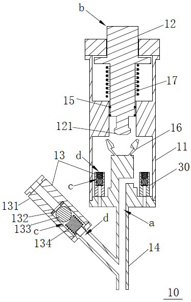
[0078] Such as figure 1 As shown, the air pressure regulating mechanism 10 for detecting body cavity pressure includes: a shell body 11 , an air pressure regulating member 12 and a first valve body 13 . The top of the shell body 11 has an opening, and the bottom is provided with a first air vent a; at least a part of the air pressure regulator 12 is located in the shell body 11, and one end protrudes from the opening as a free end b, which is used to adjust the access to and from the first vent. The amount of gas in the air vent a; wherein, the gas pressure regulator 12 and the shell body 11 are airtight; the first valve body 13 has a gas passage c arranged through; one end of the gas passage c is The second vent d is in communication with the first vent a; the other end of the gas passage c is a free end that can be sealed, and is used to connect to the test host, and when detecting body cavity pressure, it can conduct the The second vent d is connected to the test host. Th...

Embodiment 2

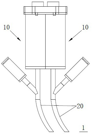
[0093] Embodiments of the present disclosure also provide a detection catheter, such as figure 2 As shown, the detection catheter 1 includes: at least one air pressure adjustment mechanism 10 and at least one sub-channel pipeline 20, the number of sub-channel pipelines 20 is adapted to the number of air pressure adjustment mechanisms 10, and each sub-channel pipeline 20 is compatible with an air pressure adjustment mechanism The first vent a of 10 communicates. The air pressure regulating mechanism 10 is any structure in the first embodiment. The number of the air pressure regulating mechanism 10 of the present disclosure can be two, three, four or more, and of course, only one can be included. Those of ordinary skill in the art should understand that the air pressure can be reasonably designed according to the needs of practical applications. The number of adjustment mechanisms is not particularly limited in the present disclosure.

[0094] According to an embodiment of th...

Embodiment 3

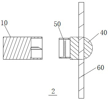
[0106] The embodiment of the present disclosure also provides a detection catheter, which is different from embodiment 2 in that the air pressure adjustment mechanism and the multi-channel pipeline are integrated in one body, so that the air pressure adjustment mechanism is also used as a consumable and cannot be reused. In the embodiment of the present disclosure, by using the sealed chamber, the multi-channel pipeline, and the seal as the main consumables, the air pressure adjustment mechanism can be reused, reducing medical waste, reducing costs, and reducing the financial burden on patients.

[0107] Such as image 3 As shown, the detection catheter 2 includes: at least one air pressure adjustment mechanism 10, at least one sub-channel pipeline, a sealed chamber 40 and at least one sealing member 50; the sealed chamber 40 and the sealing member 50 form a closed space for containing Set the sub-channel piping. Each sub-channel pipeline communicates with the first vent a of...


PUM


Abstract

The embodiment of the invention provides an air pressure adjusting mechanism for detecting pressure in the body cavity, a detection catheter and a detection device. The air pressure adjusting mechanism comprises a shell body with an opening on the top and a first air vent on the bottom; an air pressure adjusting piece of which at least a part is located in the shell body, wherein one end of the air pressure adjusting piece extending out of the opening is a free end, and used for adjusting volume of air entering and exiting the first air vent, and the air pressure adjusting piece and the shell body are in air-tight seal; and a first valve body provided with a perforating air channel, wherein one end of the air channel is a second air vent communicating with the first air vent, and the other end of the air channel is a free end capable of being sealed, used for being connected with a test host, and capable of communicating with the second air vent and the test host when the pressure in the body cavity is detected. According to the technical scheme, convenient and rapid pressure test is achieved without implementing separation-communication operation, thereby improving detection efficiency.

Description

technical field [0001] The disclosure relates to the technical field of medical devices, in particular to an air pressure adjustment mechanism, a detection catheter and a detection device for detecting body cavity pressure. Background technique [0002] With the outbreak of the global epidemic, for a large number of severe and critically ill patients with new coronary pneumonia who have respiratory failure or even progress to acute respiratory distress syndrome (ARDS), the main treatment method is to use ventilators and other equipment to help patients maintain breathing and protect the body. Oxygen supply buys time for the recovery of the immune system and the implementation of other treatments. [0003] Balancing the benefits of reducing alveolar collapse and preventing lung hyperinflation in mechanical ventilation of patients with respiratory failure / ARDS remains challenging. Estimating important parameters such as transpulmonary pressure and transdiaphragmatic pressure ...

Claims


Application Information

Patent Timeline
Patent Type & Authority Applications(China)
IPC IPC(8): A61B5/03A61B5/389A61M39/24A61M39/20A61J15/00
CPCA61B5/03A61B5/036A61B5/037A61B5/4238A61B5/4233A61B5/389A61B5/6852A61M39/24A61M39/20A61J15/0003
Inventor 桑岭刘松柴静汪会盛张志新徐远达许钊祥林志敏周静郑海崇王颖治钟南山
Owner GUANGZHOU NAT LAB
Why Eureka
Eureka Blog
Learn More