Light source optimized optical fiber testing system for power station

A technology for light source optimization and optical fiber testing, which is used in the testing of optical performance, instruments, artificial life, etc. to achieve the effect of optimizing test results and fast testing efficiency.

Pending Publication Date: 2022-01-18
国网安徽省电力有限公司亳州供电公司 +1
View PDF0 Cites 0 Cited by
  • Summary
  • Abstract
  • Description
  • Claims
  • Application Information

AI Technical Summary

Problems solved by technology

The photoelectric converter has the advantages of anti-electromagnetic interference, small size, high cost performance, and high sensitivity; it can directly or indirectly detect physical quantities such as temperature, displacement, and vibration, but the photoelectric converter has a large dependence on the spectrum of the light source

Method used


Image

  • Light source optimized optical fiber testing system for power station
  • Light source optimized optical fiber testing system for power station
  • Light source optimized optical fiber testing system for power station

Examples


Embodiment

[0099] (1), 2 fiber grating spectral overlap:

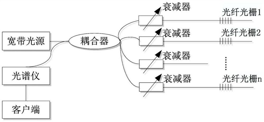
[0100] according to figure 1 The experimental platform is set up as shown. The first group of experiments uses FBG 1 and FBG 2 sensors, and their central wavelengths are 1541.398nm and 1541.743nm respectively. The fiber grating 2 is placed in a room temperature environment of 25° C., and the temperature is kept constant; the fiber grating 1 is placed in an incubator, and the temperature is adjusted to vary between 25° C. and 70° C. Adjust the response attenuation reflectivity r 1 、r 2 are 1 and 0.82, respectively.

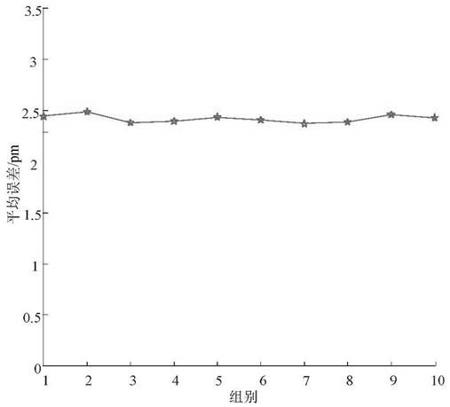
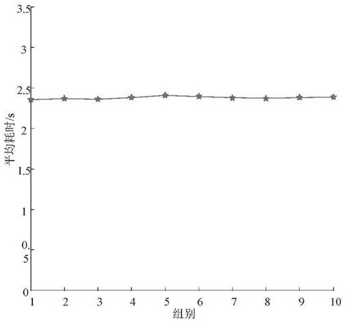
[0101] Spectra were reconstructed using the carnivore foraging method. Perform 10 calculations at 25°C-70°C and take the average value to obtain the center wavelength of each fiber grating.

[0102] Table 1 The central wavelength and error of the demodulation of two fiber gratings by the carnivore foraging method

[0103]

[0104] According to Table 1, when two FBGs have spectral overlap, the carnivore foraging...


PUM


Abstract

The invention discloses a light source optimized optical fiber testing system for a power station. The system comprises a spectrograph, optical fiber gratings, a coupler and attenuators The coupler is connected with a plurality of attenuators, each attenuator is connected with one fiber bragg grating, and the n fiber bragg grating branches are connected with the spectrograph. Light emitted by the light source enters the n fiber bragg grating branches through the coupler and then is reflected back through the fiber bragg gratings, the attenuators are used for adjusting the peak value of reflected light reflected by the fiber bragg gratings, and finally a reflection spectrum is formed in the spectrograph. The optical fiber testing system can generate light sources with different frequency spectrums; according to the optical fiber testing method, the light source and the light source frequency spectrum of the optical fiber testing system are optimally selected and controlled so that the purpose of accurately testing the attenuation of the optical fiber is achieved.

Description

technical field [0001] The invention relates to the technical field of optical fiber detection, in particular to an optical fiber testing system optimized for light sources used in power stations. Background technique [0002] Optical fiber communication technology is a communication method with light wave as the carrier and optical fiber as the transmission medium, which has a high degree of rapidity and reliability. Photoelectric composite cable is a new type of cable that combines optical cable and cable. It integrates optical fiber and power transmission copper wire as a transmission line, which can solve problems such as broadband access, equipment power consumption, and signal transmission. Photoelectric composite cables are suitable for insulated communication optical cables, transportation and communication optical cable projects, square optical cable projects, overhead optical cable construction, power optical cable engineering, high-altitude optical cable construct...

Claims


Application Information

Patent Timeline
Patent Type & Authority Applications(China)
IPC IPC(8): G01M11/02G06N3/00
CPCG01M11/02G06N3/006
Inventor 刘邦李强王亚坤蒋冬贺开放曲鸿春冯豆张赫陈祖光邓言振
Owner 国网安徽省电力有限公司亳州供电公司
Why Eureka
Try Eureka