Hydrogen fuel cell safety protection device for hydrogen hybrid commercial vehicles
A safety protection device and fuel cell technology, applied in the direction of power system fuel cells, fuel cells, fuel cell additives, etc., can solve problems such as large vibration, affecting the service life of the battery stack, and unfavorable safe use of the battery stack, achieving increased Drainage speed, avoid wet and slippery road surface, and facilitate evaporation
- Summary
- Abstract
- Description
- Claims
- Application Information
AI Technical Summary
Problems solved by technology
Method used
Image
Examples
Embodiment 1
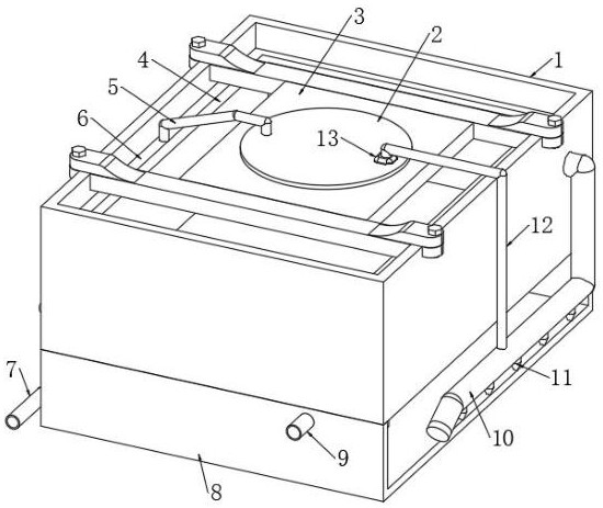
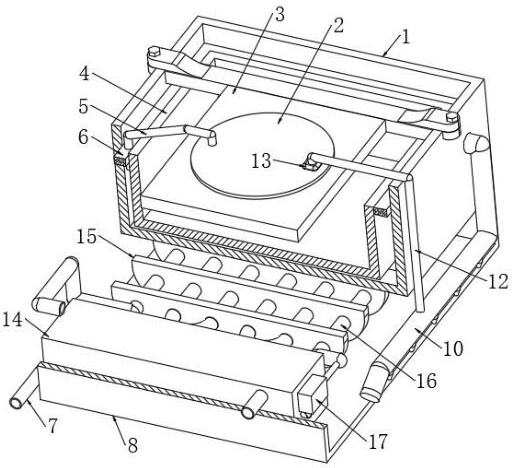
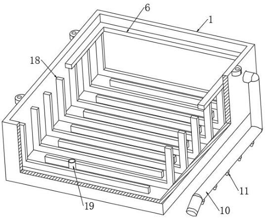
[0035] Refer to attached figure 1 - attached Figure 8 , a hydrogen fuel cell safety protection device for a hydrogen hybrid commercial vehicle, including a box body 1 and an inner liner 4, the inner edge of the upper opening of the box body 1 is fixedly connected with a rubber ring 6, and the inner liner 4 is fixed to the inner side of the rubber ring 6 Connection, the box body 1 is connected with a cooling mechanism, the cooling mechanism is connected to the lower end of the inner tank 4, the cooling mechanism uses the water produced by the fuel cell to cool the hydrogen fuel cell, and uses the inner tank 4 and the box body 1 The water pressure buffers the hydrogen fuel cell. The upper end of the box body 1 is fixedly connected with a fixed frame 3 by bolts. The hydrogen fuel cell is fixedly installed in the inner tank 4 in cooperation, and the flexible connection between the hydrogen fuel cell and the inner tank 4 is realized after fixing. The rubber ring 6 and the L-shap...
Embodiment 2
[0036] Embodiment 2: based on embodiment 1, there are differences;
[0037] Refer to attached figure 2 - attached Figure 5 , The cooling mechanism includes a shell 14, the shell 14 is fixedly connected with the lower end of the box body 1 by bolts or buckles, the upper end of the shell 14 is fixedly connected with a rubber tube 19, and the side walls of the box body 1 and the inner tank 4 are all passed through a circle. The mouth is fixedly connected with the pipe wall of the rubber tube 19, and the housing 14 is fixedly connected with a grid plate 21, and the housing 14 is fixedly connected with a plurality of evenly distributed water baffles 22 above the grid plate 21. The top of the two water baffles 22 is provided with a pressure plate 20, the pressure plate 20 is fixedly connected with the inner wall of the housing 14, the pressure plate 20 and the water baffle 22 are right-angled structures, and a plurality of evenly distributed rows are provided at the corners. Air...
Embodiment 3
[0040] Embodiment 3: based on embodiment 1, there are differences;
[0041] Refer to attached Figure 6 - attached Figure 8 , the fixing mechanism includes a fixing block 23 of cylindrical structure, the fixing mechanism in the casing 2 presses the fuel cell stack, the lower end of the casing 2 is socketed with the fixing block 23 through a through hole, and a pressure ring is sleeved on the side wall of the fixing block 23, The upper end of the pressure ring is fixedly connected with the lower end of the casing 2, the upper end of the fixed block 23 is provided with a groove, and a water bag 24 is fixedly connected in the groove, and the upper end of the water bag 24 is fixedly connected with the upper inner wall of the casing 2, and the casing 2 The upper end of the water inlet pipe 5 is fixedly connected with the water inlet pipe 5, one end of the water inlet pipe 5 is fixedly connected with the side wall of the rubber ring 6, the other end of the water inlet pipe 5 passe...
PUM
 Abstract
Description
Claims
Application Information
 - R&D
- Intellectual Property
- Life Sciences
- Materials
- Tech Scout
- Unparalleled Data Quality
- Higher Quality Content
- 60% Fewer Hallucinations
Browse by: Latest US Patents, China's latest patents, Technical Efficacy Thesaurus, Application Domain, Technology Topic, Popular Technical Reports.
© 2025 PatSnap. All rights reserved.Legal|Privacy policy|Modern Slavery Act Transparency Statement|Sitemap|About US| Contact US: help@patsnap.com


