A kind of vacuum packaging equipment for water-based varnish
A technology of vacuum encapsulation and varnish, used in packaging, liquid bottling, transportation and packaging, etc., can solve the problem of poor vacuuming efficiency, and achieve the effect of improving packaging efficiency, fast vacuuming speed and good vacuuming effect.
- Summary
- Abstract
- Description
- Claims
- Application Information
AI Technical Summary
Problems solved by technology
Method used
Image
Examples
Embodiment 1
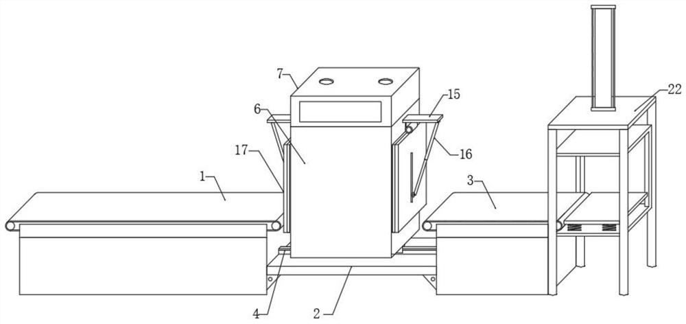
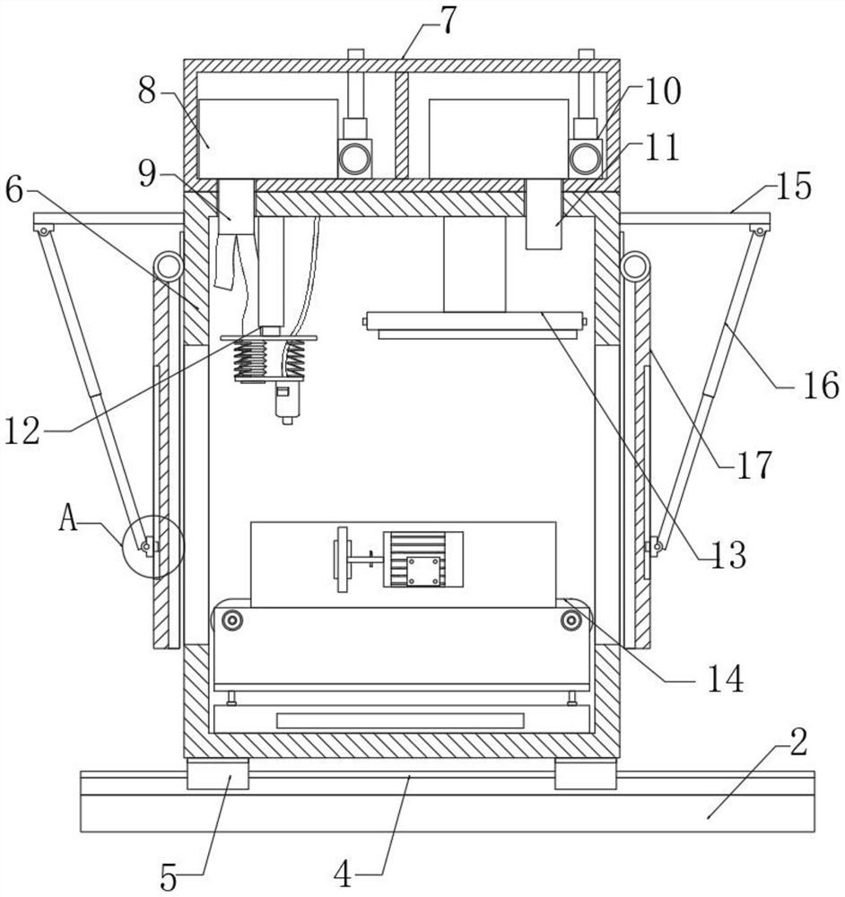
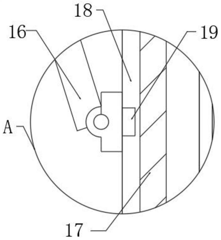
[0030] See 1- Figure 8, In the embodiment of the present invention, a vacuum packaging equipment for water-based varnish includes: conveyor belt 1; 2. An electric slide rail 4 is fixed on the upper end surface, a base 5 is slidably sleeved on the upper end of the electric slide rail 4, and a vacuum chamber 6 is fixed on the upper end of the base 5; the control cabinet 7 fixed on the upper end face of the vacuum chamber 6 is on one side of the inner cavity of the control cabinet 7 A vacuum pump 8 is installed, an intake pipe 9 is fixed at the input end of the vacuum pump 8, an intake pump 10 is installed on the other side of the inner cavity of the control cabinet 7, an exhaust pipe 11 is fixed at the output end of the intake pump 10, and the upper end of the inner cavity of the vacuum chamber 6 is fixed with a Filling assembly 12, a head module 13 is installed on the upper end of the inner cavity of the vacuum chamber 6; the conveying assembly 14 is arranged at the lower end ...
Embodiment 2
[0032] see Figure 5 , The difference from Embodiment 1 is: the upper end of the unloading frame 22 is fixed with a hydraulic rod 23, the telescopic end of the hydraulic rod 23 is installed with a lifting frame 24, and the lower end of the inner cavity of the lifting frame 24 is fixed with a spring 25, and the spring 225 is fixed on the lower end. The end face is fixed with an object storage board 26, the upper end of the lifting frame 24 is fixed with an electronic weighing apparatus 1 27 connected with the lower end surface of the object storage board 26, the lifting frame 24 is sleeved with the inner cavity of the unloading frame 22, and is used for directional lifting and moving of the lifting frame 24, the conveyor belt The loading bucket on the upper end of the second 3 can be moved to the upper end of the storage board 26, and the weight of the loading bucket can be detected by the electronic weighing instrument 1 27. The telescopic end of the hydraulic rod 2 23 moves do...
Embodiment 3
[0034] see Figure 8 The difference from Embodiment 1 is that the filling assembly 12 includes: a hydraulic rod 3 1201 fixed on the upper end of the inner cavity of the vacuum chamber 6; There are several springs 4 1203, the upper end of the spring 4 1203 is fixed with a cover plate 1202 that is sleeved with the surface of the hydraulic rod 3 1201, the lower end of the lower plate 1204 is fixed with a filling head 1205, and the extension end of the suction pipe 9 is fixed with a hose 1206. The extension end of the hose 1206 is fixed with a spring tube 1207 fitted between the cover plate 1202 and the lower plate 1204. When the loading bucket enters the vacuum chamber 6, the lower plate 1204 can be pushed into the loading bucket by the hydraulic rod 3 1201, which drives the The filling head 1205 and the input end of the spring tube 1207 enter the lower end of the inner cavity of the loading barrel, and at the same time, the larger cover plate 1202 pulls the spring four 1203 to c...
PUM
 Abstract
Description
Claims
Application Information
 - R&D
- Intellectual Property
- Life Sciences
- Materials
- Tech Scout
- Unparalleled Data Quality
- Higher Quality Content
- 60% Fewer Hallucinations
Browse by: Latest US Patents, China's latest patents, Technical Efficacy Thesaurus, Application Domain, Technology Topic, Popular Technical Reports.
© 2025 PatSnap. All rights reserved.Legal|Privacy policy|Modern Slavery Act Transparency Statement|Sitemap|About US| Contact US: help@patsnap.com


