Laser capsulorhexis device and working method thereof

A laser and laser technology, applied in the field of medical devices, can solve problems such as low accuracy of capsulorhexis shape and size, adverse symptoms, and rough edges of the capsule, achieve good surgical uniformity, reduce experience requirements, and improve accuracy and reliability sexual effect

Active Publication Date: 2022-01-28
广东麦特维逊医学研究发展有限公司
View PDF6 Cites 0 Cited by
  • Summary
  • Abstract
  • Description
  • Claims
  • Application Information

AI Technical Summary

Problems solved by technology

Doctors rely on experience to complete manual capsulorhexis operation with great uncertainty, difficulty in ensuring the uniformity of capsulorhexis, low accuracy of shape and size of capsulorhexis, and rough edges of capsulorhexis membrane, which may cause adverse postoperative symptoms in severe cases
All these operations need to be done manually after the human eye is fixed, causing great psychological pressure on the patient.

Method used


Image

  • Laser capsulorhexis device and working method thereof
  • Laser capsulorhexis device and working method thereof

Examples


Embodiment 1

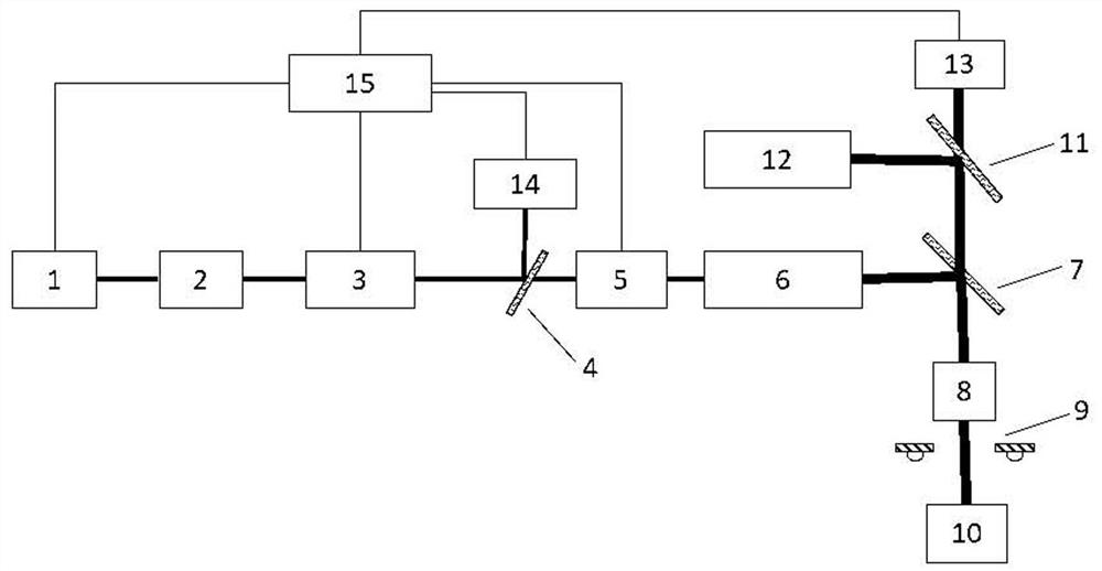
[0030] see figure 1 , is a schematic structural diagram of the laser capsulorhexis device provided in this application, including: a laser (1), a relay optical module (2), a spatial light modulator (3), a beam splitter cube (4), a vibrating mirror (5), Beam expander module (6), first dichroic mirror (7), imaging lens (8), human eye illumination light source (9), second dichroic mirror (11), optical coherence tomography module (12) ( OCT), camera (13), wavefront detection module (14) and computer (15). The computer (15) is electrically connected to the laser (1), the spatial light modulator (3), the vibrating mirror (5), the optical coherence tomography module (12), the camera (13 ) and the wavefront detection module (14).

[0031] The working mode and connection relationship of each component will be described in detail below.

[0032] Specifically, the role of the laser (1) is to provide a laser light source. It can be understood that the laser (1) emits or turns off the ...

Embodiment 2

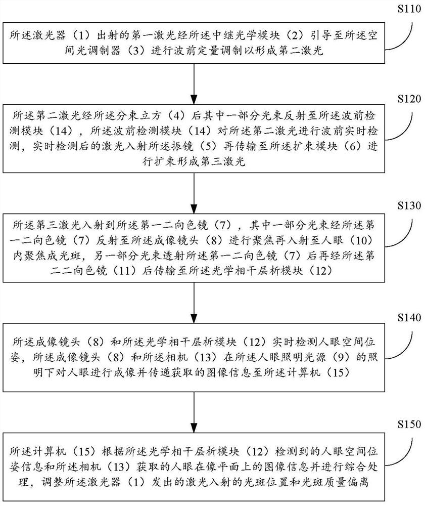
[0061] see figure 2 , a flow chart of the steps of the working method of the laser capsulorhexis device provided in Embodiment 2 of the present application, comprising the following steps:

[0062] Step S110: the first laser light emitted by the laser (1) is guided by the relay optical module (2) to the spatial light modulator (3) for quantitative wavefront modulation to form a second laser light;

[0063] Step S120: After the second laser beam passes through the beam splitter cube (4), a part of the beam is reflected to the wavefront detection module (14), and the wavefront detection module (14) waves the second laser light Before real-time detection, the laser after real-time detection is incident on the vibrating mirror (5) and then transmitted to the beam expander module (6) for beam expansion to form a third laser;

[0064] Step S130: the third laser light is incident on the first dichroic mirror (7), and a part of the light beam is reflected by the first dichroic mirro...


PUM


Abstract

The invention provides a laser capsulorhexis device which comprises a laser (1), a relay optical module (2), a spatial light modulator (3), a beam splitting cube (4), a galvanometer (5), a beam expanding module (6), a first dichroscope (7), an imaging lens (8), a human eye illumination light source (9), a second dichroscope (11), an optical coherence tomography module (12), a camera (13), a wavefront detection module (14) and a computer (15). According to the laser capsulorhexis device and the working method thereof, the human eye capsulorhexis surgical operation is achieved without a human eye interface or other devices achieving the human eye fixing function, the problem that in the traditional technology, human eyes are fixed through a human eye butt joint interface, and the accuracy of the capsulorhexis shape, size and position is difficult to guarantee during manual capsulorhexis of a doctor in the surgery is solved, anterior capsular membrane cutting is dynamically and accurately achieved in real time, the capsulorhexis operation is accurately and safely completed, and the accuracy and the reliability of the operation are greatly improved.

Description

technical field [0001] The invention belongs to the technical field of medical devices, and in particular relates to a laser capsulorhexis device and a working method thereof. Background technique [0002] In the field of lens replacement surgery, such as cataract surgery and presbyopia surgery, it is necessary to replace the patient's original lens with an artificial lens to improve vision. The most core step in the lens replacement operation is capsulorhexis, and the prior art is mainly the way of doctor's manual operation of capsulorhexis. At present, the phacoemulsification technology is very mature, and the doctor's manual nuclei fragmentation technology is also very mature. The biggest difficulty in the field of lens replacement is the capsulorhexis. Once the circular capsular bag is eccentric or too small, the capsular bag will shrink into a continuous circular capsular bag with a small diameter after operation, which will cause the intraocular lens to be eccentric, ...

Claims


Application Information

Patent Timeline
Patent Type & Authority Applications(China)
IPC IPC(8): A61F9/007A61F9/00
CPCA61F9/00754A61F9/008A61F2009/00889A61F2009/0087A61F2009/00848A61F2009/00851
Inventor 周辉曹海峰张道森王月虹
Owner 广东麦特维逊医学研究发展有限公司
Why Eureka
Try Eureka