Framing delay structure and framing delay lighting structure

A lighting structure and framing technology, which is applied in the direction of lighting devices, lighting and heating equipment, lighting device components, etc., can solve the problems of complex processing technology of time-sequence point light sources and limited use scenarios of lighting structures, and achieve compact structure, light reduction The effect of small volume and simplified composition structure

Active Publication Date: 2022-01-28
SHENZHEN UNIV
View PDF8 Cites 0 Cited by
  • Summary
  • Abstract
  • Description
  • Claims
  • Application Information

AI Technical Summary

Problems solved by technology

However, the time resolution and illumination field of view of this scheme are fixed, and the processing technology of time-sequential point light sources is relatively complicated, which limits the application scenarios of the illumination structure on the time and space scales to a certain extent.

Method used


Image

  • Framing delay structure and framing delay lighting structure
  • Framing delay structure and framing delay lighting structure
  • Framing delay structure and framing delay lighting structure

Examples


Embodiment Construction

[0082] In order to make the purpose, technical solutions and advantages of the present invention clearer, the technical solutions in the embodiments of the application will be clearly and completely described below in conjunction with the accompanying drawings in the embodiments of the application. Obviously, the described embodiments are Some embodiments of this application are not all embodiments. Based on the embodiments in this application, all other embodiments obtained by persons of ordinary skill in the art without creative efforts fall within the protection scope of this application.

[0083] The terms "first" and "second" in the description of the embodiments of the present application are used to distinguish different objects, rather than to describe a specific sequence of objects. For example, the first delay element and the second delay element are used to distinguish different delay elements, but not to describe the specific sequence of the delay elements; for ano...


PUM

PropertyMeasurementUnit
thicknessaaaaaaaaaa
lengthaaaaaaaaaa
thicknessaaaaaaaaaa

Abstract

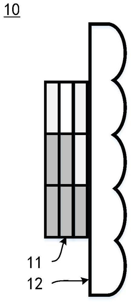
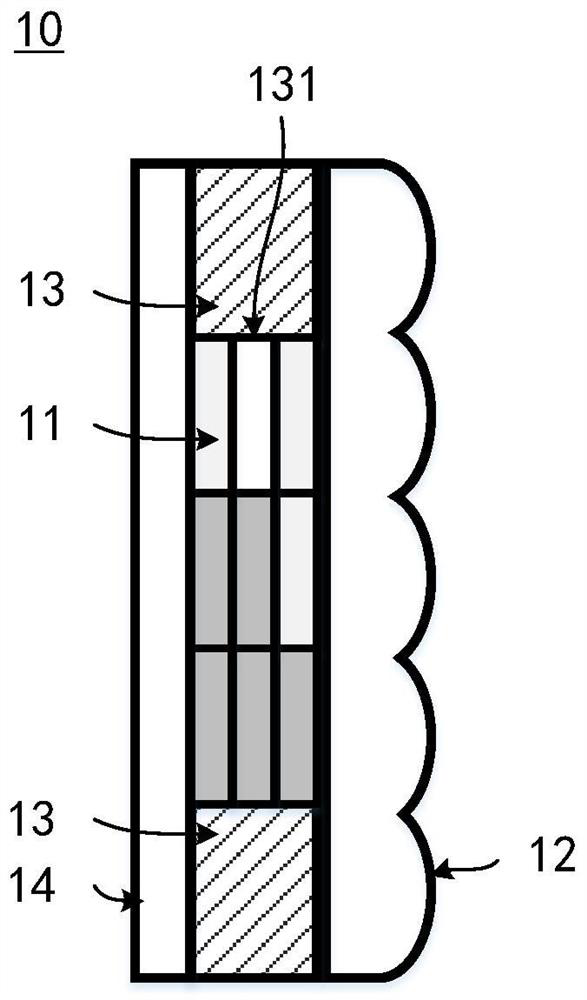
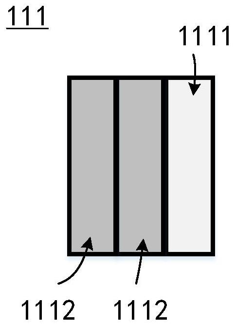
The invention discloses a framing delay structure, which comprises an optical delay assembly and a microlens array, wherein the optical delay assembly comprises a plurality of delay components, the refractive indexes of at least two delay components are different, and the light-out surface of each delay component is directly connected with the light-in surface of the microlens array. The invention further discloses a framing delay lighting structure. The technical problem of how to consider the volume of the framing delay structure and the time resolution of the framing image at least is solved.

Description

technical field [0001] The invention relates to the technical field of extremely high-speed imaging. More specifically, the present invention relates to a framing delay structure and a framing delay lighting structure. Background technique [0002] Extremely high-speed imaging technology is the main means to record the behavior changes of transient events in the atomic time (10-12 ~ 10-15s) scale, which is of great significance to basic scientific research in biology, physics, chemistry, etc. Therefore, it is widely used in materials science, nonlinear optics, plasma physics, ballistic and range research, explosion research, shock wave research and other fields that require high time and space resolution of imaging technology. [0003] With the development of the times, the demand for extremely high-speed imaging (especially the single-exposure ultra-high-speed imaging technology for non-repeatable events) is not limited to the field of scientific research, but also has a g...

Claims


Application Information

Patent Timeline
Patent Type & Authority Applications(China)
IPC IPC(8): G03B39/00G02B3/00G02B5/00F21V5/00
CPCG03B39/00G02B3/0006G02B5/00F21V5/004
Inventor 朱启凡李景镇蔡懿陆小微曾选科龙虎曾亮维朱永乐
Owner SHENZHEN UNIV
Why Eureka
Try Eureka