Integrated blade transportation frame

A transport frame, integrated technology, applied in the direction of transport and packaging, external frame, container to prevent mechanical damage, etc., can solve the problems of ship heaving, blade damage, lack of integrated bracket to transport blades in batches, etc.

Active Publication Date: 2022-02-01
中天科技集团海洋工程有限公司 +1
View PDF12 Cites 0 Cited by
  • Summary
  • Abstract
  • Description
  • Claims
  • Application Information

AI Technical Summary

Problems solved by technology

[0003] However, the existing technology lacks an integrated bracket to transport the blades in batches, whether it is vehicle transportation or sea transportation, which facilitates the placement of the blades and reduces the collision between the blades and the brackets; in particular, the general blades are transported to the At the construction site, the blades are lifted by the self-elevating platform. When the blades are just lifted off the deck, the swell impacting the hull will cause the ship to heave, which will collide with the blades, causing greater damage to the blades.

Method used


Image

  • Integrated blade transportation frame
  • Integrated blade transportation frame
  • Integrated blade transportation frame

Examples


Embodiment 1

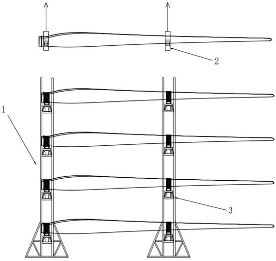
[0034] An integrated blade transport rack such as figure 1 with figure 2 As shown, it includes a pile stabilization platform support 1 and several groups of conveying bases, each blade is placed on / in a group of conveying bases, and is connected to the support 1 through the conveying base;

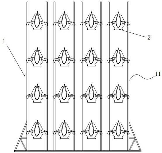
[0035] Such as figure 2 As shown, the support 1 includes a base and four sets of trusses 11 welded on the base, each set of trusses 11 is provided with four sets of sockets distributed up and down, and each set of sockets is correspondingly plugged with a set of conveying bases to place a blade. 4*4=16 blades can be transported; each group of trusses includes two vertical columns, and the sockets are fixed on the sides of the columns close to each other, so that the transport base avoids the position of the upper socket and connects to the lower socket.

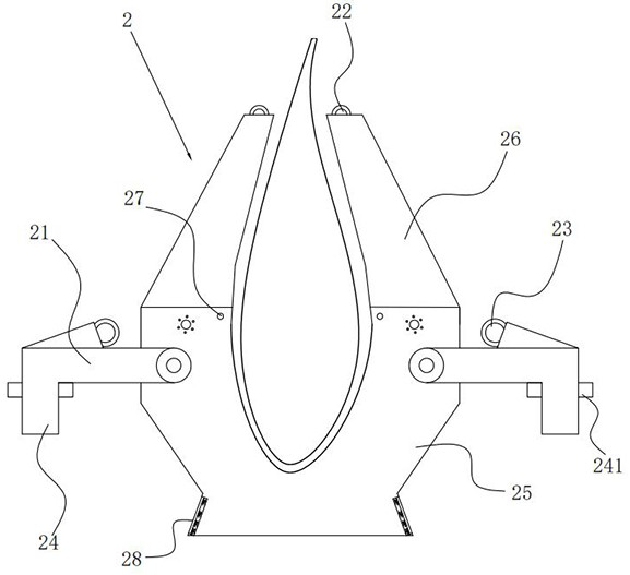
[0036] Among them, such as image 3 with Figure 5 As shown, there are two sets of conveying bases, one is connected to the root o...

Embodiment 2

[0045] This embodiment is roughly the same in structure as Embodiment 1, and the difference mainly lies in:

[0046] In order to avoid rigid collision between the plug 24 and the bracket 1 when the plug 24 is inserted into the socket, as Figure 6 As shown, several groups of buffer seats 3 are also fixed on the bracket 1, the sockets are arranged on the top of the buffer seats 3, and the delivery base is placed on the bracket 1 through the buffer seats 3;

[0047] Specifically, the buffer seat 3 includes a base plate 31, the base plate 31 is fixed on the bracket 1, and two vertical shock absorbers 32 (buffer cylinders) are connected to it, the top of the shock absorber 32 is connected to the base support plate 33, and the socket is opened on the base support. board 33.

[0048] Such as Figure 6 As shown, there are side frames 34 hinged on both sides of the bottom plate 31. The rotational position of the side frame 34 passes through the closed position and the open position....


PUM


Abstract

The invention discloses an integrated blade transportation frame, and relates to the technical field of blade conveying equipment. The integrated blade transportation frame comprises a support and a plurality of groups of conveying bases, each blade is placed on/in one group of conveying bases, and the blades are connected to the support through the conveying bases; the conveying base comprises a limiting seat and rotating arms hinged to the two sides of the limiting seat, a plurality of upper lifting lugs are arranged on the upper portion of the limiting seat, lower lifting lugs are arranged on the rotating arms, upper limiting blocks and inserting blocks are arranged on the limiting seat, a plurality of sets of inserting openings matched with the inserting blocks are formed in the support, and openings of the inserting openings are formed upwards. When the lower lifting lugs are in a lifting state, the rotating arms are driven to rotate upwards to abut against upper rotating positions below the upper limiting blocks, the rotating arm extends out of the conveying base, and the inserting block faces downwards and is matched with the opening direction of the inserting opening; and in a natural state, the rotating arm rotates downwards to lower rotating positions on the two sides of the limiting seat under the action of self weight. The effects that the blades can be transported in batches, the blades are convenient to place, meanwhile, collision between the blades and the support is reduced, and the blade transportation efficiency is improved are achieved.

Description

technical field [0001] The invention relates to the technical field of blade conveying equipment, in particular to an integrated blade conveying frame. Background technique [0002] With the increase of the state's support for the new energy industry, more and more places have begun to build offshore wind farms. Fan blades are one of the three major components of the entire wind turbine. However, due to the high cost of blades during equipment transportation, , it is necessary to ensure the safety and no collision of the blades during transportation, and to make full use of space resources during transportation to reduce transportation costs; [0003] However, the existing technology lacks an integrated bracket to transport the blades in batches, whether it is vehicle transportation or sea transportation, which facilitates the placement of the blades and reduces the collision between the blades and the brackets; in particular, the general blades are transported to the At th...

Claims


Application Information

Patent Timeline
Patent Type & Authority Applications(China)
IPC IPC(8): B65D25/24B65D61/00B65D25/10B65D81/07B65D81/05B65D25/52
CPCB65D25/24B65D61/00B65D25/101B65D81/07B65D81/05B65D25/52
Inventor 李宏龙吴春寒刘伟顾九明郑马腾
Owner 中天科技集团海洋工程有限公司
Why Eureka
Try Eureka