Self-adaptive output isolation control circuit and method

An adaptive, output isolation technology, applied to emergency protection circuit devices, electrical components, and overcurrent protection, to achieve reasonable design, increase overall machine efficiency, and reduce module costs

Pending Publication Date: 2022-02-01
SHENZHEN TIEON ENERGY TECH
View PDF0 Cites 0 Cited by
  • Summary
  • Abstract
  • Description
  • Claims
  • Application Information

AI Technical Summary

Problems solved by technology

[0010] The main purpose of the present invention is to provide an adaptive output isolation control circuit, which can solve the problem of hot plugging and quickly realize the problem of fault isolation

Method used


Image

  • Self-adaptive output isolation control circuit and method

Examples


Embodiment Construction

[0033] In order to make the technical means, creative features, goals and effects achieved by the present invention easy to understand, the present invention will be further described below in conjunction with specific embodiments.

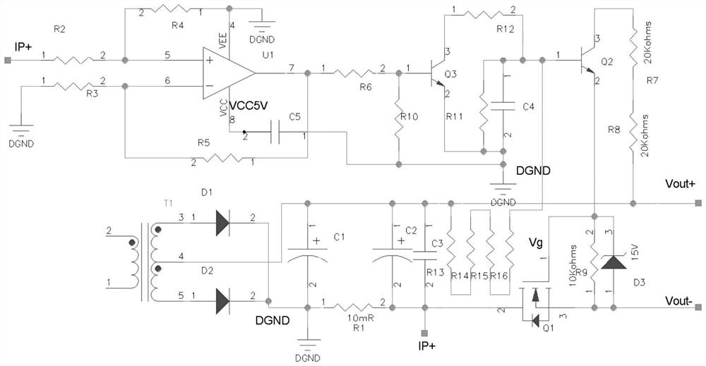
[0034] Such as figure 1 An adaptive output isolation control circuit shown includes:

[0035] An adaptive voltage divider network of the transistor Q2, the adaptive voltage divider network is connected to the base of the transistor Q2;

[0036] Slow turn-on capacitor C4, one end of the capacitor C4 is connected to the base of the triode Q2;

[0037] MOS transistor Q1 and resistors R7, resistors R8 and resistors R9 that provide an adaptive driving voltage for the MOS transistor Q1;

[0038] Diode D3, the anode of the diode D3 is connected to the source of the MOS transistor Q1, the cathode of the diode D3 is connected to the gate of the MOS transistor Q1, and the diode D3 is the driving protection of the MOS transistor Q1 diode.

[0039] Wherei...


PUM


Abstract

The invention discloses a self-adaptive output isolation control circuit, which is characterized in that an MOS (Metal Oxide Semiconductor) tube Q1 is started in a self-adaptive manner according to slow start of output voltage, so that the problem of hot plugging is solved, and the self-adaptive output isolation control circuit is enabled to work in a conducting state to the greatest extent; only when the output current is too large and the voltage is too low, the module outputs a short circuit or fault state, the MOS tube Q1 is disconnected, fault isolation between the MOS tube Q1 and a direct current bus is achieved, and no external control signal, isolation driving power supply, isolation optocoupler and the like exist.

Description

technical field [0001] The invention relates to the technical field of power electronics, in particular to an adaptive output isolation control circuit and method. Background technique [0002] Current output isolation technologies include: [0003] 1) Output diode isolation protection (usually applicable to products with low output current). [0004] 2) Positive MOS tube isolation protection (requires an external isolated drive power supply, isolated drive optocoupler). [0005] 3) Output relay isolation protection (requires isolated drive power supply). [0006] Disadvantages of existing technology: [0007] 1) Output diode isolation protection is only suitable for products with low current output; diode conduction loss is very high in high current applications. [0008] 2) The isolation protection of the positive MOS tube requires an external isolation control power supply, optocoupler and other devices, which increases the design cost and failure rate. [0009] 3) O...

Claims


Application Information

Patent Timeline
Patent Type & Authority Applications(China)
IPC IPC(8): H02H3/08H02H3/24H02H7/20
CPCH02H3/08H02H3/24H02H7/20
Inventor 王校军刘之尧曾海峰
Owner SHENZHEN TIEON ENERGY TECH
Why Eureka
Try Eureka