Fertilizing device for agricultural machinery planting and use method thereof

A fertilization device, agricultural machinery technology, applied in fertilization devices, agricultural machinery and tools, agriculture, etc., can solve the problems of unfavorable crops absorbing fertilizer, affecting the normal growth of crops, affecting the survival rate of seeds, etc., to improve the survival rate and improve fertilization The effect of using and avoiding the effect of mixed application of seeds and fertilizers

Active Publication Date: 2022-02-08
JIANGSU FOOD & PHARMA SCI COLLEGE
View PDF10 Cites 4 Cited by
  • Summary
  • Abstract
  • Description
  • Claims
  • Application Information

AI Technical Summary

Problems solved by technology

[0004] The fertilizing equipment used for agricultural machinery planting in the prior art usually uses a centrifugal fertilizer spreader for spreading, which can only be spread on the land surface, and seeds and fertilizers are mixed Applying chemical fertilizers can easily burn the seeds, affecting the survival rate of the seeds, and it cannot be fertilized deeply, which is not conducive to the root system of the crops absorbing fertilizers, affecting the normal growth of the crops, and the use effect is not good

Method used


Image

  • Fertilizing device for agricultural machinery planting and use method thereof
  • Fertilizing device for agricultural machinery planting and use method thereof
  • Fertilizing device for agricultural machinery planting and use method thereof

Examples


Embodiment 1

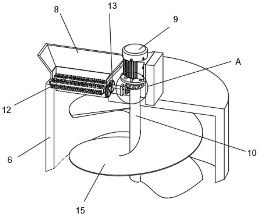
[0039] Such as Figure 1-4 As shown, a fertilizing device for agricultural machinery planting includes a support 1, a traction frame 2 is fixed on the right wall of the support 1, a plow assembly 3 is provided on the lower side of the right end of the support 1, a crushing assembly 4 is provided at the lower end of the middle part of the support 1, and the support 1 The left end is fixed with a sub-package box 5, and the upper end of the sub-package box 5 is fixed with a mixing bucket 6. The left wall of the sub-package box 5 is fixed with a rake assembly 7, and the front end of the top surface of the mixing bucket 6 is fixed with a feed hopper 8. 6 The right end of the top surface is equipped with a motor 9 through the mounting seat, and the middle part of the top surface of the mixing bucket 6 is rotatably connected with a rotating shaft A10, and the rotating shaft A10 has a vertically symmetrical structure and is fixed with two bevel gears A11, and the inside of the feeding ...

Embodiment 2

[0044] Such as Figure 5 As shown, on the basis of Embodiment 1, the crushing assembly 4 includes a crushing roller 401. The crushing roller 401 has a left-right symmetrical structure and is connected with an L-shaped rod 402 for rotation. The front and rear ends of the crushing roller 401 extend through the inner wall of the L-shaped rod 402 to The outer wall is also sleeved with a gear B403, the lower wall of the right end of the L-shaped rod 402 is provided with a rotating rod 404, the rotating rod 404 is sleeved with a gear C405, the outer end of the gear C405 is fixed with a wheel 406, and the outer wall of the L-shaped rod 402 is linear, etc. The spacing structure is provided with a plurality of positioning holes 407, the gear B403 is meshed with the gear C405, the wheel 406 is connected and fixed with the rotating rod 404, the rotating rod 404 is connected with the L-shaped rod 402 in rotation, and the L-shaped rod 402 is plugged with the bracket 1.

[0045] Two fixed b...

Embodiment 3

[0048] Such as Figure 6-9 As shown, on the basis of Embodiment 2, a groove 501 is provided on the inner bottom surface of the sub-package box 5, and the inside of the groove 501 is a left-right symmetrical structure and is rotationally connected with two distributing columns 502, and the top surface of the distributing column 502 is linear, etc. The spacing structure is provided with a plurality of distribution tanks 503, the middle part of the distribution column 502 is sleeved with a rotating shaft B506, the upper end of the middle part of the distribution tank 503 is fixed with a round tube 504, and the lower end of the rotation shaft A10 passes through the outer wall of the round tube 504 and extends to the inner wall and is socketed. Bevel gear C505 is arranged, and bevel gear D507 is socketed in the middle part of rotating shaft B506, and bevel gear C505 is engaged with bevel gear D507 and is connected. The left end of the discharge chute 308 is connected, the round pip...


PUM


Abstract

The invention relates to the technical field of agricultural planting fertilization, in particular to a fertilization device for agricultural mechanical planting and a using method thereof. The fertilization device comprises a support, a traction frame fixedly arranged on the right wall of the support, a plough assembly arranged on the lower side of the right end of the support, a crushing assembly arranged at the lower end of the middle of the support, a subpackaging box fixedly arranged at the left end of the support, and a stirring barrel fixedly arranged at the upper end of the subpackaging box; a rake assembly is fixedly arranged on the left wall of the subpackaging box; a feeding hopper is fixedly arranged at the front end of the top surface of the stirring barrel. According to the invention, the motor rotates to drive a crushing roller to crush agglomerated and large-particle fertilizer, the fertilizer is mixed and stirred by a spiral stirring blade, the fertilizer falls into the subpackaging box and then is conveyed into a discharging groove by the discharging pipe, and at the moment, the discharging groove enables the fertilizer to fall into ploughed gully land, so that deep ploughing and fertilization are completed. The seed integrity is protected, the survival rate of the seeds is improved, crops can conveniently and directly absorb fertilizer from root systems through deep ploughing and fertilization, favorable conditions are provided for crop growth, and the fertilization use effect of agricultural planting is remarkably improved.

Description

technical field [0001] The invention relates to the technical field of fertilization for agricultural planting, in particular to a fertilizing device for agricultural machinery planting and a method for using the same. Background technique [0002] Agricultural machinery refers to various machinery used in crop planting and animal husbandry production, as well as in the primary processing and handling of agricultural and animal products. Agricultural machinery includes agricultural power machinery, farmland construction machinery, soil tillage machinery, planting and fertilization machinery, plant protection machinery, farmland drainage and irrigation machinery, crop harvesting machinery, agricultural product processing machinery, animal husbandry machinery and agricultural transportation machinery, etc. Agricultural machinery in a broad sense also includes forestry machinery, fishing machinery, and rural sideline machinery such as sericulture, beekeeping, and edible fungus ...

Claims


Application Information

Patent Timeline
Patent Type & Authority Applications(China)
IPC IPC(8): A01B49/06A01C15/00A01C15/06B02C4/02
CPCA01B49/065A01C15/005A01C15/06B02C4/02
Inventor 王卫兵
Owner JIANGSU FOOD & PHARMA SCI COLLEGE
Why Eureka
Try Eureka