Blue light and infrared dual-wavelength coaxial composite laser additive manufacturing device and method

A technology of laser additive manufacturing and manufacturing equipment, which is applied in the direction of additive manufacturing, additive processing, and improvement of process efficiency. It can solve problems such as reducing the density of molded parts, powder adhesion on the surface of molded parts, and affecting molding accuracy and surface roughness. , to reduce the temperature gradient of the molten pool, reduce the surface roughness, and improve the molding quality

Pending Publication Date: 2022-02-08
SOUTH CHINA UNIV OF TECH
View PDF5 Cites 3 Cited by
  • Summary
  • Abstract
  • Description
  • Claims
  • Application Information

AI Technical Summary

Problems solved by technology

[0005] The high laser reflectivity makes the powder material unable to obtain enough input energy, and it is difficult for the laser to continuously melt the metal powder material during the molding process, resulting in the generation of defects such as pores, reducing the density of the molded part, and finally seriously affecting the overall performance of the molded part
[0006] In addition, when infrared lasers are used as energy sources, in order to ensure sufficient input energy, it is usually necessary to use high laser power and low scanning speed for printing, resulting in low molding efficiency, increased manufacturing costs, and waste of energy
[0007] At the same time, the spot diameter of the infrared laser after focusing can still reach 50 microns. The heat-affected area brought by the spot during the molding process is relatively large, causing the powder to adhere to the surface of the molded part, which affects the molding accuracy and surface roughness.

Method used


Image

  • Blue light and infrared dual-wavelength coaxial composite laser additive manufacturing device and method
  • Blue light and infrared dual-wavelength coaxial composite laser additive manufacturing device and method
  • Blue light and infrared dual-wavelength coaxial composite laser additive manufacturing device and method

Examples


Embodiment

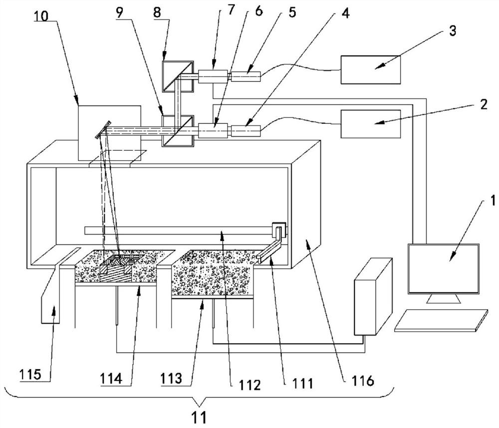
[0045] Such as Figure 1-3 shown. The invention discloses a blue-light infrared dual-wavelength coaxial composite laser additive manufacturing device, which includes a computer system 1, a molding cavity 11 and a laser;

[0046] The laser includes: an infrared laser 2, a blue laser 3, an infrared collimator 4, a blue collimator 5, an infrared dynamic focusing mirror 6, a blue dynamic focusing mirror 7, a blue reflector 8, a beam combiner 9, a scanning Galvanometer 10;

[0047] The infrared laser 2, the infrared light collimating mirror 4, the infrared light dynamic focusing mirror 6, the beam combiner 9 and the scanning vibrating mirror 10 are sequentially connected in an optical path;

[0048] The blue light laser 3, the blue light collimator 5, the blue light dynamic focusing mirror 7, the blue light reflector 8, the beam combiner 9 and the scanning vibrating mirror 10 are sequentially connected in an optical path.

[0049] The beam combiner 9 is a dichroic mirror, one si...


PUM


Abstract

The invention discloses a blue light and infrared dual-wavelength coaxial composite laser additive manufacturing device and method. The device comprises a computer system, a forming cavity and a laser. The laser comprises an infrared laser, a blue laser, an infrared collimating lens, a blue collimator, an infrared dynamic focusing lens, a blue dynamic focusing lens, a blue reflector, a beam combiner and a scanning galvanometer, wherein the infrared laser, the infrared collimating lens, the infrared dynamic focusing lens, the beam combiner and the scanning galvanometer are sequentially connected through a light path; and the blue laser, the blue collimator, the blue dynamic focusing lens, the blue reflector, the beam combiner and the scanning galvanometer are sequentially in light path connection. Two lasers with different wavelengths are coaxially coupled and output, the laser absorptivity of the material can be improved by adopting short-wavelength blue light, and the laser power loss is reduced; and meanwhile, a light beam with a smaller focusing spot diameter is obtained and is used for high-precision forming work of metal parts.

Description

technical field [0001] The invention relates to the field of laser additive manufacturing, in particular to a blue-light infrared dual-wavelength coaxial composite laser additive manufacturing device and method. Background technique [0002] Laser powder bed fusion molding technology, also known as Selective Laser Melting (SLM), uses a finely focused laser spot to directly melt 15-53 μm metal powder to achieve metallurgical bonding. It has high processing accuracy, close to 100% density, and surface quality Higher and many other advantages, it is one of the important technologies of metal additive manufacturing. [0003] With the development of laser additive manufacturing technology and the expansion of application fields, related engineering applications put forward higher requirements for molding quality. Especially with the application of high-reflective materials laser additive manufacturing parts, its processing technology puts forward new requirements for equipment p...

Claims


Application Information

Patent Timeline
Patent Type & Authority Applications(China)
IPC IPC(8): B22F12/45B22F12/41B22F10/28B33Y30/00B22F12/13B22F10/362B22F10/364B33Y10/00
CPCB22F12/45B22F12/41B22F10/28B33Y30/00B22F12/13B22F10/362B22F10/364B33Y10/00Y02P10/25
Inventor 王迪陈晓君邓国威韦雄棉杨永强
Owner SOUTH CHINA UNIV OF TECH
Why Eureka
Try Eureka