
Cylindrical battery liquid injection hole aligning method and system

A cylindrical battery and liquid injection hole technology, which is applied to battery pack components, circuits, electrical components, etc., can solve the problems of high battery production scrap rate, high production cost, high product scrap rate, etc., and improve the inspection pass rate , Improve the qualified rate of hole alignment and improve the efficiency of liquid injection

Pending Publication Date: 2022-02-08
HEFEI GUOXUAN HIGH TECH POWER ENERGY
View PDF6 Cites 1 Cited by
  • Summary
  • Abstract
  • Description
  • Claims
  • Application Information

AI Technical Summary

Problems solved by technology

[0002] At present, the production process of lithium-ion batteries, the liquid injection process of cylindrical batteries, and the battery production scrap rate are extremely high, resulting in high production costs.
The liquid injection positioning of existing equipment is mainly based on mechanical positioning. The pole is clamped by a mechanical device, and the battery is grabbed and rotated by a manipulator. However, due to the stable rotation accuracy of the equipment, when the equipment is injected, the positioning is always inaccurate, resulting in The product scrap rate is high, and secondly, some equipment adopts the CCD hole alignment method, but in the application process, due to the environmental impact, the pass rate of the hole alignment is low, which seriously affects the production efficiency
[0003] The Chinese invention patent application with the publication number CN103682238A discloses a liquid injection hole structure and a liquid injection method for a lithium-ion battery. The accurate positioning of the liquid injection nozzle of the liquid injection machine and the battery can realize the accurate positioning of the liquid injection nozzle of the liquid injection machine and the liquid injection hole of the cover plate. It is also based on mechanical positioning, so there is still a problem of high product scrap rate

Method used


Image

  • Cylindrical battery liquid injection hole aligning method and system
  • Cylindrical battery liquid injection hole aligning method and system
  • Cylindrical battery liquid injection hole aligning method and system

Examples


Embodiment Construction

[0054] In order to facilitate those skilled in the art to understand the technical solution of the present invention, the technical solution of the present invention will be further described in conjunction with the accompanying drawings.

[0055] The terms "first" and "second" are used for descriptive purposes only, and cannot be understood as indicating or implying relative importance or implicitly specifying the quantity of indicated technical features. Thus, a feature defined as "first" and "second" may explicitly or implicitly include one or more of these features. In the description of the present application, "plurality" means two or more, unless otherwise specifically defined.

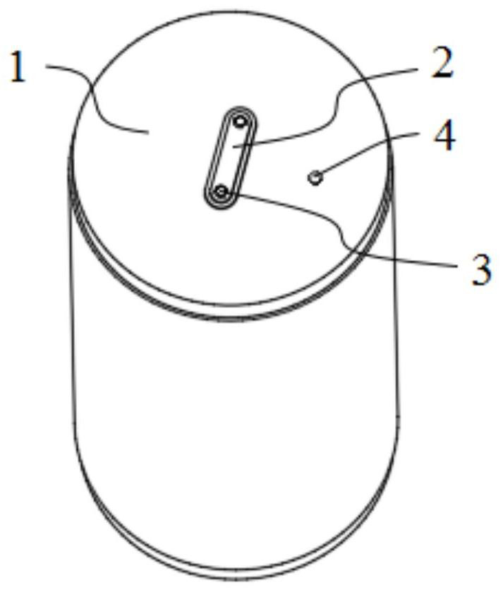
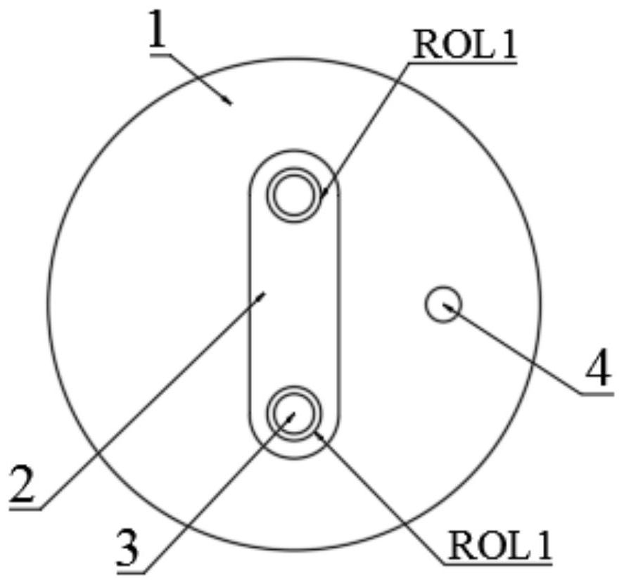
[0056] refer to figure 1 , in the present embodiment, it is cylindrical battery 1 that needs liquid injection hole to hole, and pole 2, nail 3 and liquid injection hole 4 are arranged on it, and pole 2 is located at the center of the upper end of cylindrical battery 1, and pole 2 is Long stri...


PUM


Abstract

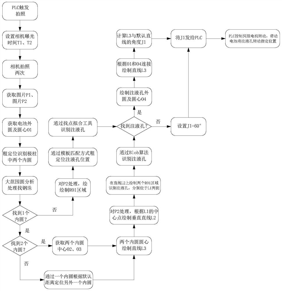
The invention discloses a cylindrical battery liquid injection hole aligning method and system, and the method comprises the following steps: S1, photographing the upper end of a cylindrical battery through a camera, obtaining a picture of the cylindrical battery, and uploading the picture to a processor; S2, on the basis of the picture of the cylindrical battery obtained in the step S1, firstly finding out the positions of screws at the two ends of a pole by using an image processing algorithm, then finding out the position of a liquid injection hole, and sending the current angle of the liquid injection hole to a PLC; and S3, controlling the servo motor by the PLC to drive the cylindrical battery to rotate, and rotating the liquid injection hole to a designated position. According to the hole aligning method, through a mode of firstly finding the screws at the two ends of the pole and then finding the liquid injection hole, misjudgment caused by the edge of the pole can be reduced, the hole aligning qualification rate can be greatly improved, and the production efficiency can be improved.

Description

technical field [0001] The invention relates to the technical field of battery liquid injection holes, in particular to a method and system for aligning cylindrical battery liquid injection holes. Background technique [0002] At present, the lithium-ion battery production process, the liquid injection process of the cylindrical battery cell, and the battery production scrap rate are extremely high, resulting in high production costs. The liquid injection positioning of existing equipment is mainly based on mechanical positioning. The pole is clamped by a mechanical device, and the battery is grabbed and rotated by a manipulator. However, due to the stable rotation accuracy of the equipment, when the equipment is injected, the positioning is always inaccurate, resulting in The product scrap rate is high, and secondly, some equipment adopts the CCD hole alignment method, but in the application process, due to the environmental impact, the pass rate of the hole alignment is lo...

Claims


Application Information

Patent Timeline
Patent Type & Authority Applications(China)
IPC IPC(8): H01M50/609G06T7/70
CPCH01M50/609G06T7/70G06T2207/10004G06T2207/20104Y02E60/10
Inventor 黄立军戚孟荣杨中舒武行兵
Owner HEFEI GUOXUAN HIGH TECH POWER ENERGY
Learn More