
A High Common-Mode Rejection Ratio Differential Antenna Based on Half-Mode Substrate Integrated Waveguide

A technology of half-mode substrate integration and high common-mode rejection, which is applied in the field of antennas and electromagnetic waves, can solve problems such as reducing antenna radiation efficiency, improve beamwidth consistency, improve antenna performance, and avoid feeding network intersections.

Active Publication Date: 2022-05-31
BEIHANG UNIV
View PDF8 Cites 0 Cited by
  • Summary
  • Abstract
  • Description
  • Claims
  • Application Information

AI Technical Summary

Problems solved by technology

[0003] The feeder design of the differential antenna usually adopts the form of a power divider. For the feeding requirements of the same diagonal phase, there must be a cross point in the differential feeder. At this time, probes or other forms are required to ensure the signal of each differential feeder. Integrity, but this method greatly reduces the radiation efficiency of the antenna

Method used


Image

  • A High Common-Mode Rejection Ratio Differential Antenna Based on Half-Mode Substrate Integrated Waveguide
  • A High Common-Mode Rejection Ratio Differential Antenna Based on Half-Mode Substrate Integrated Waveguide
  • A High Common-Mode Rejection Ratio Differential Antenna Based on Half-Mode Substrate Integrated Waveguide

Examples


Embodiment Construction

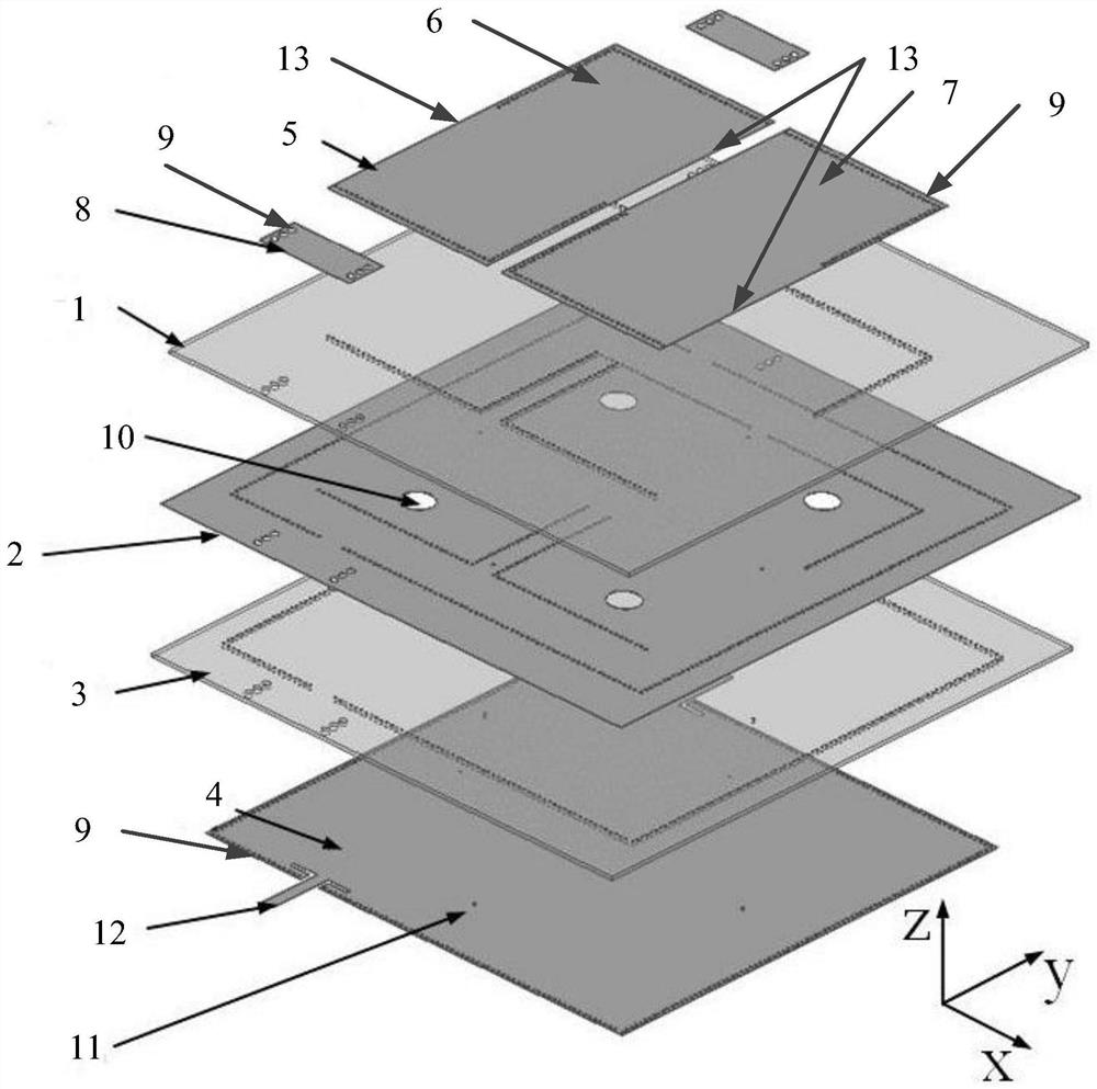
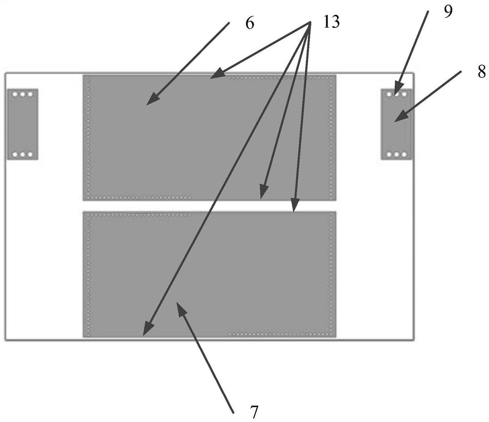
[0036] The reconstructed half-mode substrate-integrated waveguide cavity has the same resonant frequency and the radiating magnetic walls 13 at opposite positions,

[0037] As shown in Figure 6, Figure 6(a) is the radiation pattern of the reconstructed half-mode substrate integrated waveguide cavity, and the antenna is only at a distance of two

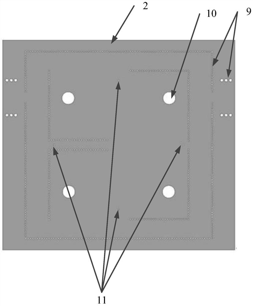
[0038] As shown in FIG. 7, FIG. 7(a) is a schematic diagram of the electric field distribution of the perturbation via 11 not loaded with metal. The present invention uses a cavity

[0040] As shown in Figure 10, Figure 10(a) shows the E-plane and Figure 10(b) shows that the cross-polarization of the H-plane is -43.3 dB, respectively

[0042] The above are only preferred embodiments of the present invention, and it should be understood that the present invention is not limited to those disclosed herein.


PUM

PropertyMeasurementUnit
dielectric lossaaaaaaaaaa

Abstract

The invention relates to a high common-mode rejection ratio differential antenna based on a half-mode substrate integrated waveguide, which includes an upper dielectric plate, a metal floor and a lower dielectric plate arranged in sequence from top to bottom; on the upper surface of the upper dielectric plate A reconstructed half-mode substrate integrated waveguide component is provided, which constitutes the radiator of the antenna. By combining two reconstructed half-mode substrate integrated waveguides to form components, the radiation gain and uniformity of the antenna are increased; the lower dielectric plate The lower surface is provided with a square substrate integrated waveguide and fed through the coplanar waveguide; four coupling feeding holes are etched on the metal floor for coupling the signal from the square substrate integrated waveguide cavity to the reconstruction half. Die-substrate-integrated waveguide components. The invention adopts the cavity coupling feeding mode, which avoids the occurrence of feed network intersections and improves the performance of the antenna; the common-mode suppression is relatively high, and the double-order common-mode suppression is realized by coupling the cavity and the radiator, and by introducing perturbation common-mode rejection is further improved.

Description

A High Common Mode Rejection Ratio Differential Antenna Based on Half Mode Substrate Integrated Waveguide technical field The present invention relates to antenna and electromagnetic wave technical field, relate in particular to a kind of high-common Mode rejection ratio differential antenna. Background technique [0002] With the rapid development of modern wireless radio frequency systems towards miniaturization, multi-function and intelligence, military The problem of electromagnetic interference between devices in the civil field and the civil field is becoming more and more prominent; the differential technology can effectively reduce the electromagnetic interference between the devices, and the interference The interference signal has the same coupling effect on the two feeders of the differential antenna, and the difference between the two ports makes the differential antenna effective The input value remains unchanged; the differential antenna can be directly c...

Claims


Application Information

Patent Timeline
Patent Type & Authority Patents(China)
IPC IPC(8): H01Q1/38H01Q1/48H01Q1/50
CPCH01Q1/38H01Q1/48H01Q1/50
Inventor 陈爱新付学东张哲孙铭宇秦葭湄
Owner BEIHANG UNIV
Learn More