High-strength end face positioning compact turbine rotor device of turbocharger

A turbocharger and turbine rotor technology, which is applied to pump devices, components of pumping devices for elastic fluids, machines/engines, etc. To solve problems such as long length, cumbersome inspection and assembly processes, etc., to reduce the difficulty of processing, reduce the difficulty of manufacturing and material costs, and reduce the failure mode of shafting

Active Publication Date: 2022-02-11
WEIFANG UNIV OF SCI & TECH
View PDF11 Cites 3 Cited by
  • Summary
  • Abstract
  • Description
  • Claims
  • Application Information

AI Technical Summary

Problems solved by technology

[0005] 1. The axial length of the rotor shaft of the turbine rotor 8 is too long, the processing procedure is complicated, the machining time is long, the processing efficiency is affected, the material is wasted, and the processing cost is high
[0006] 2. When the turbine rotor 8 fails and is damaged, the main cause is the stress concentration caused by the change in the diameter of the rotor shaft at the positioning shoulder 19. The diameter of the impeller mating shaft 20 is too small, and the disturbance is large; eventually resulting in the high-speed operation of the compressor impeller 3 and the turbine rotor 8 are unstable and broken, so the variable-diameter turbine rotor 8 has a large quality hidden danger
[0007] 3. There are many kinds of components in the traditional turbine rotor 8-axis system, and the accumulated errors between the components are relatively large. The machining accuracy of multiple components can only be controlled through stricter processing technology, resulting in cumbersome subsequent inspection and assembly procedures. Lead to high manufacturing and assembly costs of the finished supercharger

Method used


Image

  • High-strength end face positioning compact turbine rotor device of turbocharger
  • High-strength end face positioning compact turbine rotor device of turbocharger
  • High-strength end face positioning compact turbine rotor device of turbocharger

Examples


Embodiment

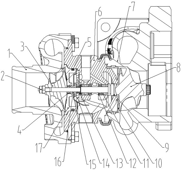
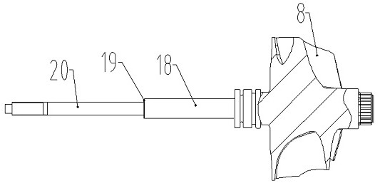
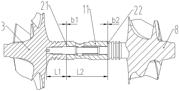
[0037] Example: See Figure 3-8A high-strength end surface of a turbocharger is positioned, including a floating bearing 11, a central portion of the floating bearing 11 having a bearing internal hole 45 having a turbine rotor 8 on one side of the floating bearing 11, One side of the turbine rotor 8 is integrated with a rotor shaft 18, and one end of the rotor shaft 18 is fitted within the bearing inner hole 45, and the other side of the floating bearing 11 is mounted with a compressor impeller 3, and the carrier impeller. 3 is integrally connected to one side of the floating bearings 11, and the rotor shaft 18 is fixed to the impeller shaft 67 to achieve torque and rotation transfer.

[0038] The rotor shaft 18 includes the application function thereof including the rotor shaft body 181, a first rotor support portion 26, a rotor oil storage portion 31, a second rotor support portion 261, a rotor support portion 26, a rotor support portion 261, a second rotor support portion 26, a ...


PUM


Abstract

The invention discloses a high-strength end face positioning compact turbine rotor device of a turbocharger. The device comprises a floating bearing, a bearing inner hole is formed in the middle of the floating bearing, a turbine rotor is installed on one side of the floating bearing, a rotor shaft is integrally connected to one side of the turbine rotor, one end of the rotor shaft is assembled in the bearing inner hole, an air compressor impeller is installed on the other side of the floating bearing, an impeller shaft is integrally connected to the side, close to the floating bearing, of the air compressor impeller, and the rotor shaft and the impeller shaft are fixedly connected to achieve torque and rotation transmission. According to the high-strength end face positioning compact turbine rotor device of the turbocharger, the machining difficulty of the turbine rotor and the number of shaft system parts can be reduced, and the manufacturing difficulty and the material cost can be reduced; the number of parts of the turbocharger can be reduced, the bearing reliability and the bearing efficiency can be greatly improved, and shaft system faults are reduced.

Description

Technical field [0001] The present invention belongs to the technical field of turbocharger, in particular, to a high-strength end surface of a turbocharger, a compact turbine rotor device. Background technique [0002] The turbocharger has gradually formed its own inherent structure by the development of the past few decades; this basic curing supercharger structure, the bearing system is more complicated, the number of parts and the number of components used, the accuracy of processing, The assembly requirements are also very high. [0003] The overall structure of the existing turbocharger is figure 1 and figure 2 As shown, the main components of the existing turbocharger include a compressor case 1, a locking nut 2, a compressor impeller 3, a press-end sealing ring 4, an intermediate housing seal 5, an intermediate 6, a turbine shell 7, Turbine rotor 8, the vortex seal ring 9, the heat insulation cover 10, the floating bearing 11, the support sleeve 12, the thrust sleeve 13, ...

Claims


Application Information

Patent Timeline
Patent Type & Authority Applications(China)
IPC IPC(8): F04D25/04F04D29/26F04D29/053F04D29/057F04D29/28F01D15/08F01D5/02F01D5/06F01D25/16
CPCF04D25/045F04D29/263F04D29/053F04D29/057F04D29/284F01D15/08F01D5/02F01D5/06F01D25/16Y02T10/12
Inventor 李延昭张林营姜卫国翟彦春董琳赵德彪
Owner WEIFANG UNIV OF SCI & TECH
Why Eureka
Try Eureka