
Electrocatalytic oxidation treatment method for foam discharge gas recovery wastewater

A technology for electrocatalytic oxidation and gas extraction wastewater, which is applied in water/sewage treatment, chemical instruments and methods, neutralized water/sewage treatment, etc. effect of effect

Pending Publication Date: 2022-02-15
PUYANG TIANDIREN ENVIRONMENTAL PROTECTION TECH CO LTD
View PDF5 Cites 0 Cited by
  • Summary
  • Abstract
  • Description
  • Claims
  • Application Information

AI Technical Summary

Problems solved by technology

[0005] Aiming at the deficiencies of the prior art, the present invention provides an electrocatalytic oxidation treatment method for bubble exhaust gas production wastewater, which solves the problem that the existing treatment method cannot perform electrocatalytic oxidation well, and the efficiency is low when mixed precipitation is carried out. The problem of not meeting people's requirements

Method used

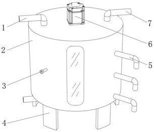
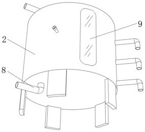
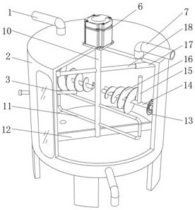

Image

  • Electrocatalytic oxidation treatment method for foam discharge gas recovery wastewater
  • Electrocatalytic oxidation treatment method for foam discharge gas recovery wastewater
  • Electrocatalytic oxidation treatment method for foam discharge gas recovery wastewater

Examples


Embodiment 1

[0038] refer to Figure 1-4 , an electrocatalytic oxidation treatment method for bubble exhaust gas extraction wastewater, comprising the following steps:

[0039] S1: Collection tank, collect the waste water from bubble exhaust gas production into the collection tank, and then carry out sedimentation treatment;

[0040] S2: Homogeneous receiving tank, the settled sewage is passed into the homogeneous receiving tank, and then the free oil obtained from the upper part of the gravity separation is recovered and stored in the waste oil recovery tank, and the other bubbles are drained for collection;

[0041] S3: coagulation and sedimentation, leading the treated bubble drainage into the coagulation device for coagulation treatment;

[0042] S4: Electrolytic oxidation tank, the treated sewage is introduced into the electrolytic tank, and then electrocoagulation treatment is carried out under the action of direct current with aluminum, iron and other metals as anodes;

[0043] S5...

Embodiment 2

[0052] refer to Figure 1-4 , an electrocatalytic oxidation treatment method for bubble exhaust gas extraction wastewater, comprising the following steps:

[0053] S1: Collection tank, collect the waste water from bubble exhaust gas production into the collection tank, and then carry out sedimentation treatment;

[0054] S2: Homogeneous receiving tank, the settled sewage is passed into the homogeneous receiving tank, and then the free oil obtained from the upper part of the gravity separation is recovered and stored in the waste oil recovery tank, and the other bubbles are drained for collection;

[0055] S3: coagulation and sedimentation, leading the treated bubble drainage into the coagulation device for coagulation treatment;

[0056] S4: Electrolytic oxidation tank, the treated sewage is introduced into the electrolytic tank, and then electrocoagulation treatment is carried out under the action of direct current with aluminum, iron and other metals as anodes;

[0057] S5...


PUM


Abstract

The invention relates to the technical field of foam drainage wastewater treatment, and discloses an electrocatalytic oxidation treatment method for foam drainage gas production wastewater, which comprises the following steps: s1, collecting the foam drainage gas production wastewater into a collecting tank, and then carrying out precipitation treatment; s2, a homogeneous receiving tank: introducing the settled sewage into the homogeneous receiving tank, recovering free oil obtained at the upper part through gravity separation, storing the free oil in a dirty oil recovery tank, and collecting other bubble drainage water; s3, coagulating sedimentation: introducing the treated foam drainage water into a coagulation device for coagulation treatment; and s4, treatment with an electrolytic oxidation pond. According to the method, high-salt-tolerance microorganisms are adopted to carry out biochemical treatment on the soaking drainage water. The treatment process is simple, the energy consumption is low, and various substances in the bubble drainage water can be thoroughly treated. In addition, through cooperative use of a poke rod and a spiral sheet, stirring and mixing of mixed wastewater are realized, and the mixing effect of the device is improved.

Description

technical field [0001] The invention relates to the technical field of bubble drainage wastewater treatment, in particular to an electrocatalytic oxidation treatment method of bubble drainage gas production wastewater. Background technique [0002] With the continuous development of gas fields and the improvement of reserves production, the water production of gas reservoirs and the number of water production wells are increasing, and problems such as fluid accumulation in wellbore and water production of gas wells affecting normal production have gradually emerged. Fluid accumulation in the wellbore will increase the back pressure on the gas layer and limit the production capacity of the well. If the fluid accumulation in the wellbore is too large, the gas well will stop blowing completely. In addition, the liquid column in the wellbore will damage the formation near the wellbore, reduce the gas phase permeability, and seriously affect the ultimate recovery of the gas field...

Claims


Application Information

Patent Timeline
IPC IPC(8): C02F9/14C02F101/30
CPCC02F9/00C02F2001/007C02F1/40C02F1/463C02F1/5236C02F1/66C02F3/30C02F1/4672C02F1/50C02F1/283C02F1/001C02F1/56C02F2101/30C02F2303/14
Inventor 王跃刚茆明军郭敏唐建李伟平王晓红骆翼梦陈琦吴振峰许菲
Owner PUYANG TIANDIREN ENVIRONMENTAL PROTECTION TECH CO LTD
Learn More