External oil lubricating mechanism for separator
A technology of lubricating mechanism and separator, which is applied in the direction of engine lubrication, lubricating oil container, lubricating parts, etc., which can solve the problems of large size of self-contained oil tank lubricating structure, not very practical, delaying production efficiency, etc.
- Summary
- Abstract
- Description
- Claims
- Application Information
AI Technical Summary
Problems solved by technology
Method used
Image

Examples
Embodiment 1
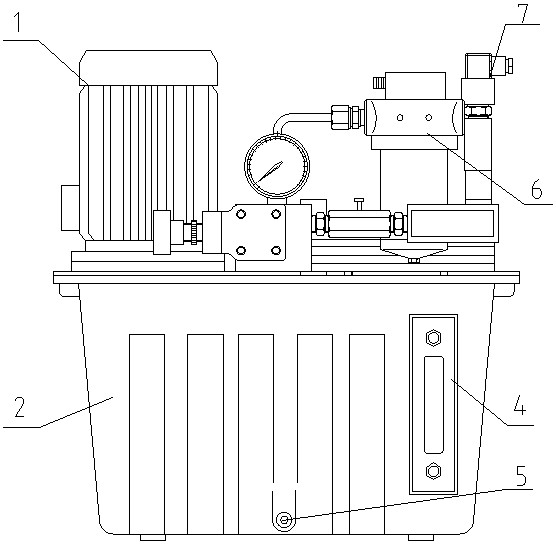
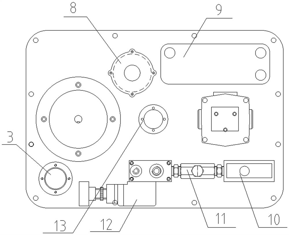
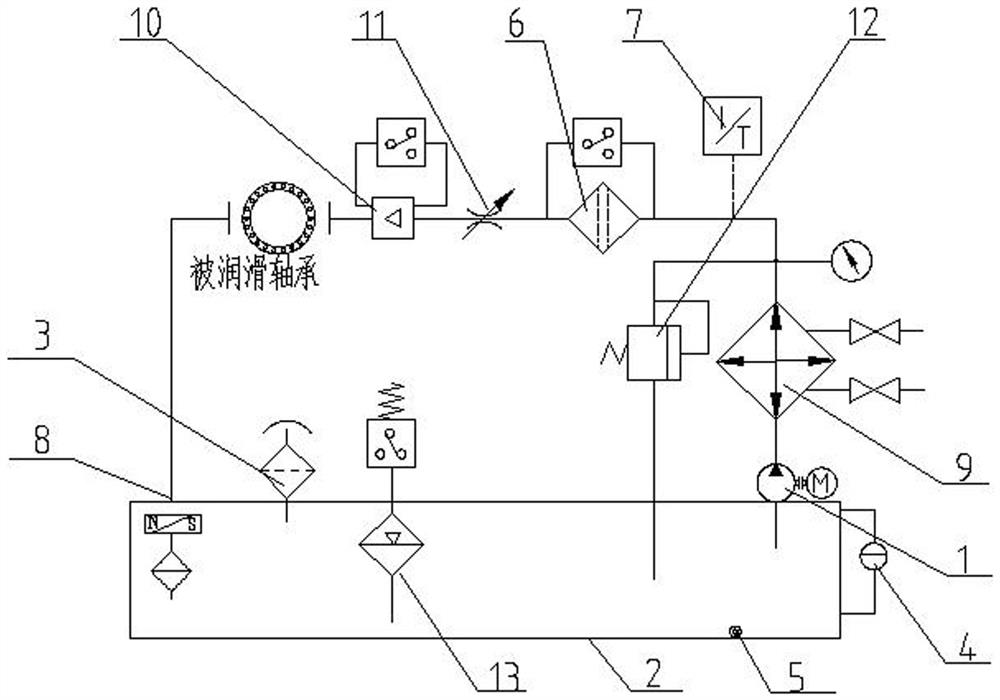
[0025] refer to Figure 1-3 , an external oil lubrication mechanism for a separator, including a separator bearing and an oil tank 2, the top of the oil tank 2 is sequentially provided with an oil pump 1, a heat exchanger 9, a temperature sensor 7, an overflow valve 12, a filter 6, a throttling Valve 11 and flow meter 10, the input end of oil pump 1 communicates with the oil outlet of oil tank 2, the output end of oil pump 1 communicates with the input end of heat exchanger 9, the output end of heat exchanger 9 communicates with the input of overflow valve 12 The output end of the overflow valve 12 is connected with the input end of the filter 6, the output end of the filter 6 is connected with the input end of the throttle valve 11, and an oil return port 8 is opened on the top side of the oil tank 2 to throttle The output end of the valve 11 communicates with the oil return port 8 through the oil return pipe, and one end of the separator shaft is connected with the throttle ...
Embodiment 2
[0028] refer to Figure 1-3 , the temperature sensor 7 is fixedly connected to one side of the heat exchanger 9 through a bolt rod, and the oil pump 1, the heat exchanger 9, the overflow valve 12, the filter 6, the throttle valve 11 and the flow meter 10 are all connected to the top of the oil tank 2 The connection is detachable. There is an oil discharge port at the bottom of one side of the fuel tank 2, and the oil drain plug 5 is fixedly connected to the edge of the oil discharge port by bolts. The top side of the fuel tank 2 is provided with an oil filling port 3. An oil seal cover is detachably connected. One side of the fuel tank 2 is provided with an oil level sight glass 4. One side of the fuel tank 2 is provided with an installation groove for installing the oil level sight glass 4 and running through one side of the fuel tank 2. The top center of the fuel tank 2 An oil level gauge 13 is provided, and the oil pump 1 is a centrifugal pump or a gear pump.
[0029] To s...
PUM
 Abstract
Description
Claims
Application Information
 - R&D
- Intellectual Property
- Life Sciences
- Materials
- Tech Scout
- Unparalleled Data Quality
- Higher Quality Content
- 60% Fewer Hallucinations
Browse by: Latest US Patents, China's latest patents, Technical Efficacy Thesaurus, Application Domain, Technology Topic, Popular Technical Reports.
© 2025 PatSnap. All rights reserved.Legal|Privacy policy|Modern Slavery Act Transparency Statement|Sitemap|About US| Contact US: help@patsnap.com