High-temperature particle waste heat recycling device and method for waste incineration power plant

A technology of waste incineration and waste heat recovery, applied in the direction of combustion method, heating method, steam engine device, etc., can solve the problems of low-temperature heat loss of tail gas exhaust, waste of resources, heat loss of boiler combustion, etc., to increase heat supply and heat supply income, reduce cooling water consumption, and improve economic efficiency

Pending Publication Date: 2022-02-15
HUANENG CLEAN ENERGY RES INST +1
View PDF0 Cites 0 Cited by
  • Summary
  • Abstract
  • Description
  • Claims
  • Application Information

AI Technical Summary

Problems solved by technology

[0004] Although incineration has significant advantages in the harmless treatment of municipal solid waste, there are still some key problems to be solved. The most common problem is that the overall energy efficiency of waste incineration power plants is low, and there is a large loss of low-grade energy. The main reason is the heat loss of boiler combustion and the low temperature heat loss of exhaust gas
In addition, the bottom ash particles at the bottom of the incinerators in waste incineration power plants also contain large waste heat energy, but the current waste incineration power plants rarely use this part of heat
In the prior art, the heat in the high-temperature particles at the bottom of the incinerator in the waste incineration power plant has not been utilized, but only the waste heat in the flue gas is used, and the energy utilization rate is low, resulting in waste of resources

Method used


Image

  • High-temperature particle waste heat recycling device and method for waste incineration power plant

Examples


Embodiment Construction

[0023] The present invention will be further described in detail below in conjunction with specific embodiments, which are explanations of the present invention rather than limitations.

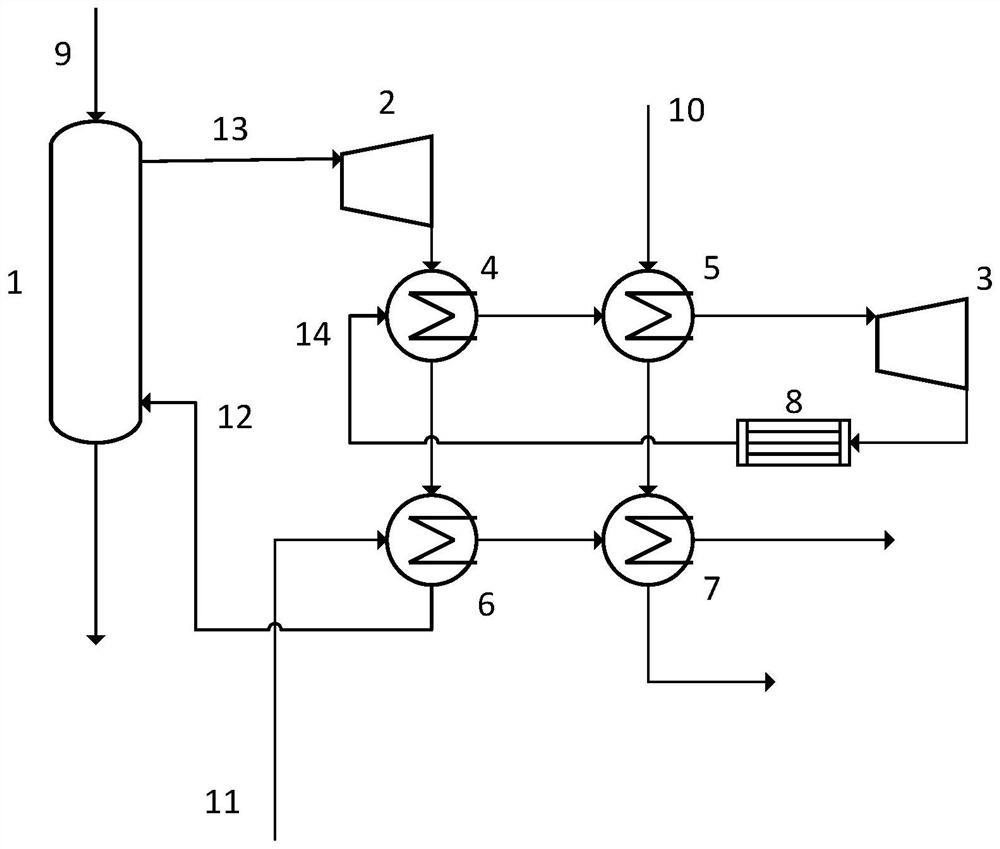
[0024] A waste heat recovery and utilization device for high-temperature particles in a waste incineration power plant, including a waste heat boiler 1 connected to the bottom of the incinerator in the waste incineration power plant, and the waste heat boiler 1 is used to exchange heat with the high-temperature particles 9 at the bottom of the incinerator in the waste incineration power plant. heat exchange.

[0025] The outlet of the heat exchange medium of the waste heat boiler 1 is connected to the inlet of the first steam turbine 2, and the bottom of the waste heat boiler 1 is provided with a particle recovery device for processing and recovering the high temperature particles 9 after heat exchange. The outlet of the first steam turbine 2 communicates with the first inlet of the first hea...


PUM


Abstract

The invention discloses a high-temperature particle waste heat recycling device and method for a waste incineration power plant. The high-temperature particle waste heat recycling device comprises a waste heat boiler, wherein the waste heat boiler is communicated with the bottom of an incinerator of the waste incineration power plant, and the waste heat boiler is used for exchanging heat with high-temperature particles at the bottom of the incinerator of the waste incineration power plant through a heat exchange medium; a heat exchange medium outlet of the waste heat boiler is communicated with an inlet of a first steam turbine, an outlet of the first steam turbine is communicated with a first inlet of a first heat exchanger, a first outlet of the first heat exchanger is connected with a first inlet of a third heat exchanger, and a first outlet of the third heat exchanger is connected with a heat exchange medium inlet of the waste heat boiler to form a steam Rankine cycle; and a second outlet of the first heat exchanger is connected with a second inlet of a second heat exchanger, a second outlet of the second heat exchanger is communicated with an inlet of a second steam turbine, and an outlet of the second steam turbine is communicated with a second inlet of the first heat exchanger to form an organic Rankine cycle.

Description

technical field [0001] The invention belongs to the technical field of garbage power generation, in particular to a device and method for recovering and utilizing waste heat of high-temperature particles in a garbage incineration power plant. Background technique [0002] Landfill used to be the main way to dispose of waste. Its advantages are simple operation and low cost. The disadvantage is that it occupies a large area. In the long run, the landfill leachate generated during the landfill process is difficult to handle, which will cause land in the area And groundwater resources are polluted, and with the advancement of urbanization, landfills are under increasing pressure. [0003] Waste incineration power generation is to release the chemical energy stored in domestic waste through incineration, convert it into heat energy and use it. Compared with landfill, the emission of polluting gases from waste incineration is much lower. At the same time, the electricity and hea...

Claims


Application Information

Patent Timeline
Patent Type & Authority Applications(China)
IPC IPC(8): F23G5/46F24D18/00F24D19/00F01K11/02F01D15/10F24D101/10
CPCF23G5/46F24D19/00F01K11/02F01D15/10F23G2206/203Y02E20/12
Inventor 安航周贤彭烁钟迪蔡浩飞姚国鹏白烨黄永琪王会
Owner HUANENG CLEAN ENERGY RES INST
Why Eureka
Try Eureka