Heat pipe type SCR denitration reactor and low-temperature sulfur-containing flue gas denitration method thereof
A technology of denitrification reactor and heat pipe type, which is applied in chemical instruments and methods, separation methods, gas treatment, etc., can solve the problems of easy deactivation of catalysts and low efficiency of SCR denitrification, and achieve good axial uniformity and good reactor layout. Flexible, fast heat transfer effect
- Summary
- Abstract
- Description
- Claims
- Application Information
AI Technical Summary
Problems solved by technology
Method used
Image
Examples
Embodiment 1
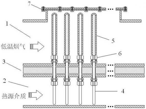
[0026] The structure of the heat pipe type SCR denitrifact reactor of the present embodiment is figure 1As shown, the heat pipe type SCR denitrifact reactor of the present embodiment includes a reactor body, and a reactor body is provided with a flue 1, and the reactor is located below the flue 1, a heat source medium passage 2, a smoke The road 1 and the heat source dielectric channel 2 average extension, the flue 2 and the heat source dielectric channel 2 are provided with a heat insulating layer 3, and the heat insulating layer 3 is between the lower wall surface of the flue 1 and the upper wall surface of the heat source medium passage 2. The heat insulating material is configured, and the heat pipe array is vertically disposed in the reactor. The heat pipe array contains several heat pipes 4, and each of the heat pipes 4 in the heat pipe is 3 three in the smoking 1, the insulation layer 3 and the heat source medium passage 2. Horizontal space, the heat pipe 4 perpendicular to...
Embodiment 2
[0030] The heat pipe type SCR denitration reactor of this embodiment differs from Example 1 only in the construct of the denitrifination catalyst layer. The base body of the decision catalyst layer 5 of the present embodiment is a hollow tube having a thickness of 1 to 10 mm porous ceramic, and the catalyst passes through vacuum. The impregnated or coated manner is loaded on the porous ceramic substrate, and the catalyst layer 5 is formed to form a porous structure after drying and calcining, and the denitrifination catalyst layer 5 is nestled on the heat pipe condensation section. Other structures of the heat pipe type SCR denitrifact reactor of the present embodiment are the same as in Example 1, and will not be described herein.
[0031] In other embodiments of the invention, the connection between the heat pipe 4 and the upper wall surface of the flue 1 and the upper wall surface of the heat source dielectric channel 2 may have a plurality of sealing connections in the form of...
specific Embodiment
[0035] Specific embodiments of the low temperature sulfur flue gas denitration method of the present invention, such as:
[0036] A specific embodiment of the heat pipe type SCR denitrifact reactor of the present invention is used for a low temperature sulfur flue gas denitrifting method, which includes the following steps: (1) containing NO x Low-temperature smoke (usually less than 250 ° C) flows from the upper flue 1, when the low-temperature smoke gas flows through the denitrification catalyst layer 5, the NO is completed under the action of the catalyst. x Selective catalytic reduction removal; (2) At the same time, the heat source medium flows from the heat source dielectric channel 2, and the temperature of the heat source medium is higher than the flue gas temperature in the flue, and the heat source medium temperature reaches the sulfur temperature of the denitrifination in the catalyst layer 5; (3) The evaporation section of the heat pipe 4 absorbs the heat of the heat s...
PUM
| Property | Measurement | Unit |
|---|---|---|
| thickness | aaaaa | aaaaa |
| thickness | aaaaa | aaaaa |
Abstract
Description
Claims
Application Information
 - R&D
- Intellectual Property
- Life Sciences
- Materials
- Tech Scout
- Unparalleled Data Quality
- Higher Quality Content
- 60% Fewer Hallucinations
Browse by: Latest US Patents, China's latest patents, Technical Efficacy Thesaurus, Application Domain, Technology Topic, Popular Technical Reports.
© 2025 PatSnap. All rights reserved.Legal|Privacy policy|Modern Slavery Act Transparency Statement|Sitemap|About US| Contact US: help@patsnap.com

