Automatic sealing equipment for medical children capsules
An automatic sealing and capsule technology, which is applied in packaging sealing/fastening, external support, transportation packaging, etc., can solve the problems of plastic film scalding and affecting the sealing effect, so as to improve the yield rate, save time and labor, and improve work efficiency. The effect of work efficiency
- Summary
- Abstract
- Description
- Claims
- Application Information
AI Technical Summary
Problems solved by technology
Method used
Image

Examples
Embodiment 1
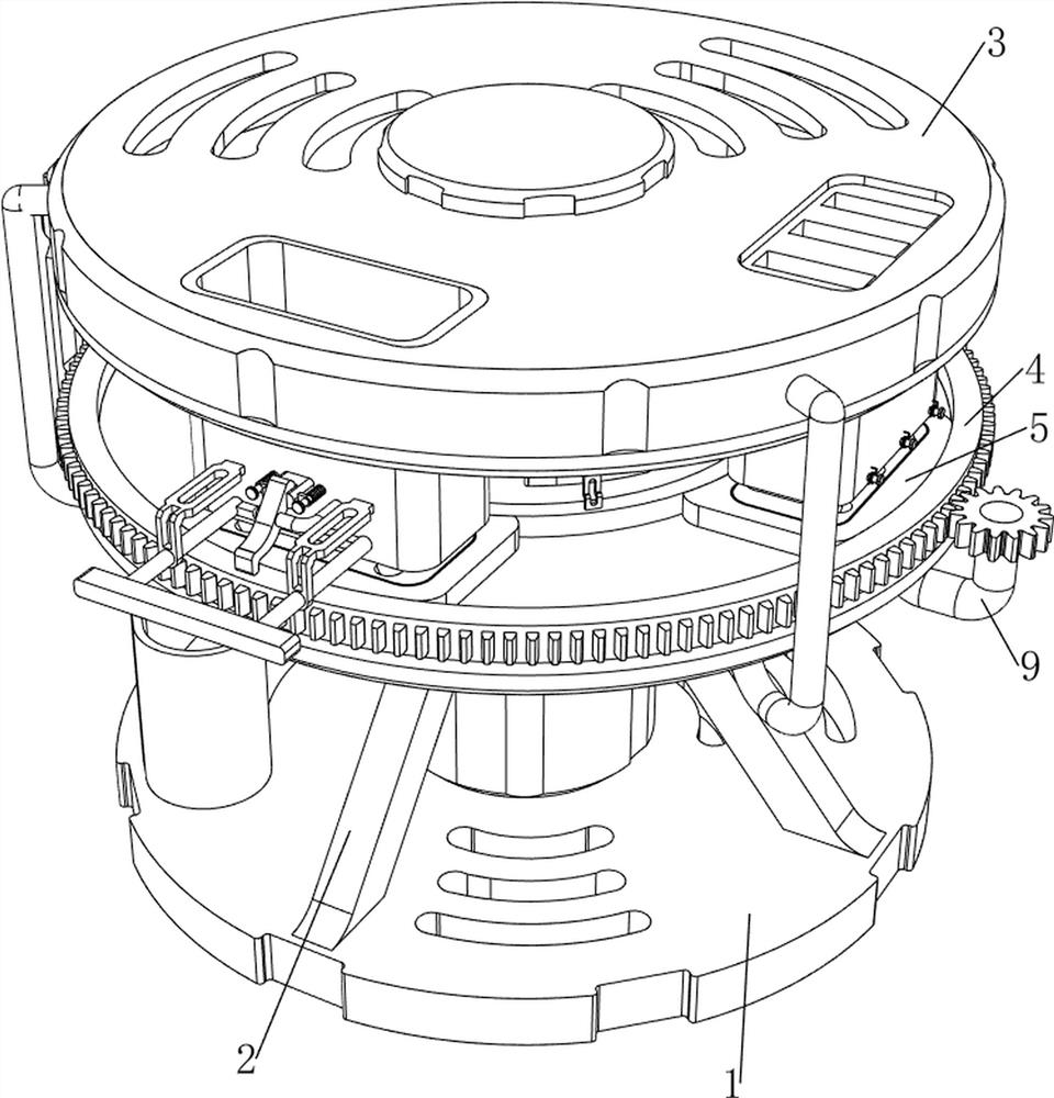
[0034] A kind of automatic sealing equipment for medical children's capsules, such as Figure 1-Figure 5 As shown, it includes a bottom plate 1, a support frame 2, a machine cover 3, a gear plate 4, a movable block 5, a first fixed rod 6, a pressing rod 61, a roller 7, a rotary block 8, a power mechanism 9 and a pressing mechanism 10 , the top of the bottom plate 1 is connected with a support frame 2, the upper part of the support frame 2 is connected with the organic cover 3, the upper middle part of the support frame 2 is rotatably connected with a toothed disc 4, the inside of the toothed disc 4 is connected with a movable block 5 along the circumferential direction, and the top of the support frame 2 The left and right sides are all connected with the first fixed rod 6 at the rear, the bottom of the first fixed rod 6 on the right side is connected with a pressure rod 61, and the first fixed rod 6 on both sides is connected with the roller 7 in a rotational manner, and the f...
Embodiment 2
[0039] On the basis of Example 1, such as Image 6 As shown, it also includes a first unloading mechanism 11, and the first unloading mechanism 11 includes a second support plate 111, a first material storage frame 112, a third support plate 113, a movable rod 114, a support rod 115, a rotating plate 116, spring 117 and slide rod 118, the middle part of the front side of the support frame 2 is connected with the second support plate 111, the upper front part of the second support plate 111 is connected with the first material storage frame 112, the left and right sides of the first material storage frame 112 The bottom of the front part is connected with a third support plate 113, and the middle part of the lower side of the third support plate 113 on both sides is slidingly connected with the lower side of the front part of the first material storage frame 112. A movable rod 114 is connected, and the lower part of the front side of the first material storage frame 112 The rig...
Embodiment 3
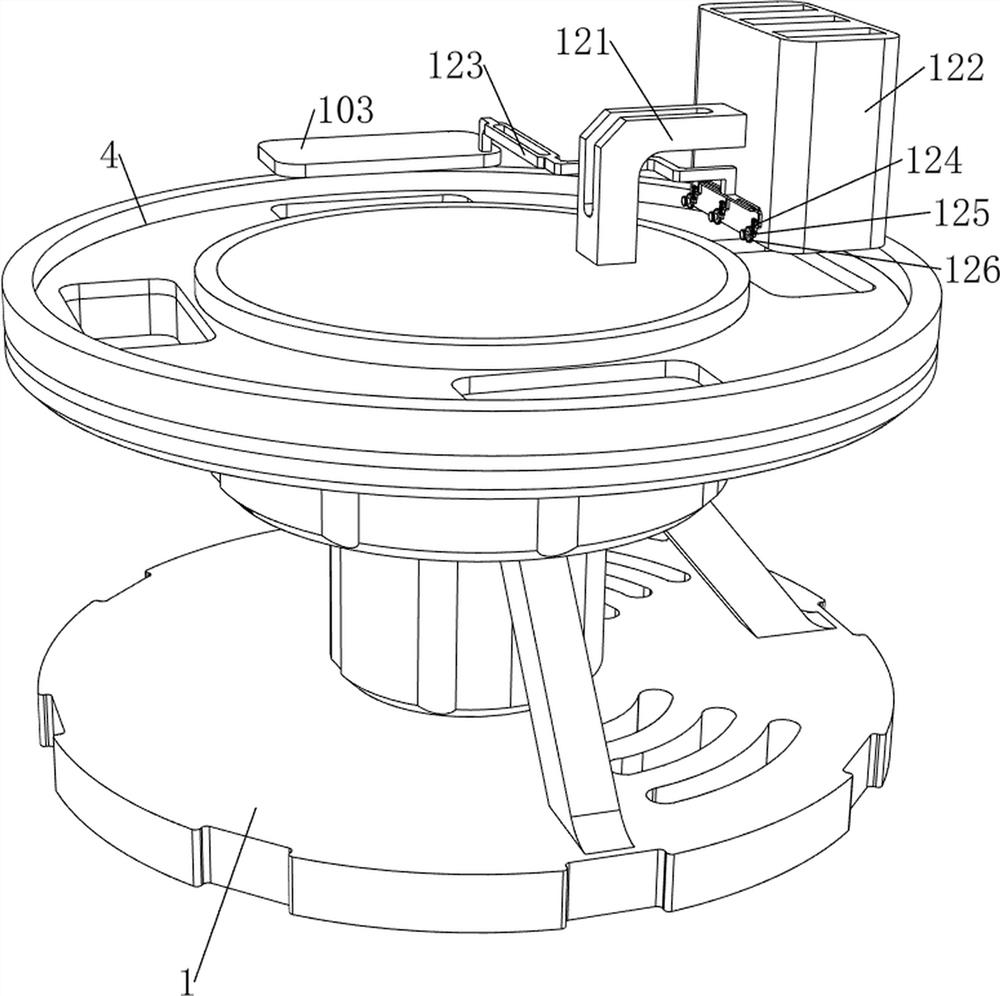
[0042] On the basis of Example 2, such as Figure 7 with Figure 8 As shown, it also includes a second unloading mechanism 12, and the second unloading mechanism 12 includes a fourth support plate 121, a second material storage frame 122, a fifth support plate 123, a spine 124, a first rotating shaft 125, a Two ratchet gears 126 and the second torsion spring 127, the right side of the top of the support frame 2 is connected with the fourth support plate 121, the right side of the fourth support plate 121 is connected with the second material storage frame 122, and the right side of the top of the cutting board 103 is connected There is a fifth support plate 123, three spines 124 are connected to the lower right side of the fifth support plate 123, three first rotating shafts 125 are connected to the left side of the lower side of the second material storage frame 122, and three first rotating shafts 125 are connected to the middle part. The second ratchet gear 126 is connecte...
PUM
 Abstract
Description
Claims
Application Information