Fallen leaf treatment device for botanical garden
A processing device and gardening technology, applied in grain processing, solid waste removal, drilling equipment, etc., can solve the problems of reducing drilling efficiency, reducing decomposition efficiency, and reducing stacking efficiency, so as to improve stacking efficiency and decomposition Efficiency, convenient and fast decomposition effect
- Summary
- Abstract
- Description
- Claims
- Application Information
AI Technical Summary
Problems solved by technology
Method used
Image

Examples
Embodiment 1
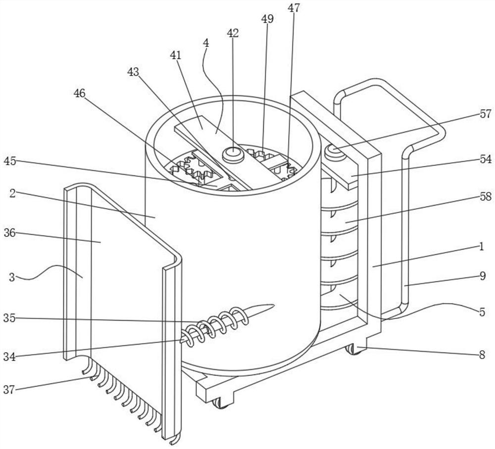
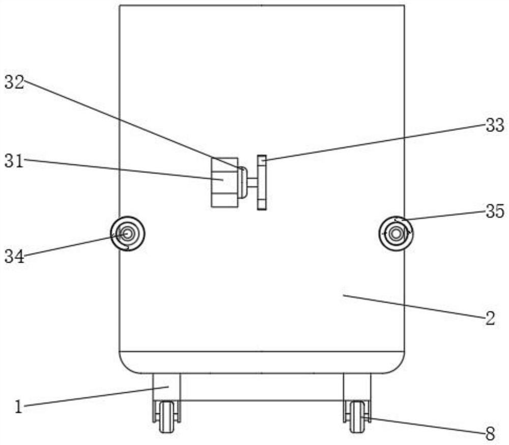
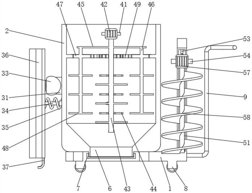
[0027] see Figure 1-2 , the present invention provides a technical solution: a fallen leaf processing device for plant gardens, comprising a support base body 1, a collection tank 2, a pusher assembly 3, a crushing assembly 4 and a drilling assembly 5, the top outer wall of the support base body 1 A collection tank 2 is fixed by welding, a pushing assembly 3 is fixed on one side of the collection tank 2, a crushing assembly 4 is fixed on one side of the collection tank 2, and a drill is fixed on one side of the inner wall of the main body 1 of the support seat. hole assembly 5; the bottom outer wall of the collection tank 2 is connected with a discharge pipe 6, and the bottom outer wall of the discharge pipe 6 is threadedly connected with a cover 7, unscrew the cover 7, and then pass through the discharge pipe 6 to crush the The fallen leaves are discharged, which improves the discharge efficiency; rollers 8 are installed on the bottom outer wall of the support seat main body...
Embodiment 2
[0031] see image 3, the crushing assembly 4 includes a support plate 41, a second motor 42, a first rotating shaft 43, a first cutting plate 44, a rotating plate 45, a second rotating shaft 46, a gear 47, a second cutting plate 48 and an internal toothed ring 49, collect A support plate 41 is welded and fixed on one side top inner wall of the tank 2, a second motor 42 is mounted on the middle inner wall of the support plate 41, a first rotating shaft 43 is installed on the middle inner wall of the collection tank 2, and the second motor 42 The bottom end of the output shaft is welded on the outer wall of the first rotating shaft 43, the first cutting plate 44 is distributed and installed on the outer wall of one side of the first rotating shaft 43, and the rotating plate 45 is welded and fixed on the outer wall of the top of one side of the first rotating shaft 43. The inner wall of the bottom end of the plate 45 is distributed and rotatably connected with a second rotating s...
Embodiment 3
[0034] see Figure 4-5 , the drilling assembly 5 includes a chute 51, a third motor 52, a threaded rod 53, a lifting plate 54, a slider 55, a threaded hole 56, a fourth motor 57 and a drill bit 58, and the outside of the support seat main body 1 is equipped with a lifting Plate 54, slide block 55 is all welded and fixed on the both sides outer walls of lifting plate 54, and corresponding slide block 55 is all opened with chute 51 on the both sides inner walls of support seat main body 1, and the bottom end inner wall of chute 51 is inlaid with The third motor 52, the top inner wall of the chute 51 is rotatably connected with a threaded rod 53, and the top end of the output shaft of the third motor 52 is fixed on the outer wall of the threaded rod 53, and the inner wall of one side of the slider 55 corresponds to the threaded rod 53 A threaded hole 56 is provided, a fourth motor 57 is inlaid on one side inner wall of the lifting plate 54, a drill bit 58 is installed on the bott...
PUM
 Abstract
Description
Claims
Application Information
 - Generate Ideas
- Intellectual Property
- Life Sciences
- Materials
- Tech Scout
- Unparalleled Data Quality
- Higher Quality Content
- 60% Fewer Hallucinations
Browse by: Latest US Patents, China's latest patents, Technical Efficacy Thesaurus, Application Domain, Technology Topic, Popular Technical Reports.
© 2025 PatSnap. All rights reserved.Legal|Privacy policy|Modern Slavery Act Transparency Statement|Sitemap|About US| Contact US: help@patsnap.com