
Drain-source voltage detection circuit and drain-source voltage detection method

A drain-source voltage and detection circuit technology, which is applied in the direction of only measuring voltage, measuring current/voltage, measuring devices, etc., can solve the problems of increased circuit cost, reduced detection accuracy, and complicated circuit structure, so as to improve detection accuracy, Effect of reducing circuit cost and simplifying circuit structure

Active Publication Date: 2022-02-25
HALO MICROELECTRONICS CO LTD
View PDF6 Cites 2 Cited by
  • Summary
  • Abstract
  • Description
  • Claims
  • Application Information

AI Technical Summary

Problems solved by technology

[0003] Generally, a drain-source voltage detection circuit is used to detect when the inductor current and the drain voltage reach the bottom of the resonance valley, but in the current traditional drain-source voltage detection technology, a resistor divider or a capacitor or an auxiliary winding is generally used to sense the voltage of the main switch tube. Drain voltage, but the traditional drain-source voltage detection technology needs to add external components to realize the detection of the drain voltage of the main switching tube. Since the sensing needs to be carried out in a noisy PCB environment, the external components may be in the normal switching time. It is easy to generate noise coupling with other traces, thereby reducing the accuracy of detection, and adding additional external components will make the entire circuit structure complicated and the circuit cost increased

Method used


Image

  • Drain-source voltage detection circuit and drain-source voltage detection method
  • Drain-source voltage detection circuit and drain-source voltage detection method
  • Drain-source voltage detection circuit and drain-source voltage detection method

Examples


Embodiment Construction

[0065] In order to make the object, technical solution and advantages of the present invention clearer, the present invention will be further described in detail below in conjunction with the accompanying drawings and embodiments. It should be understood that the specific embodiments described here are only used to explain the present invention, not to limit the present invention. Based on the embodiments of the present invention, all other embodiments obtained by persons of ordinary skill in the art without making creative efforts belong to the protection scope of the present invention.

[0066] It should be noted that, if there is no conflict, various features in the embodiments of the present invention may be combined with each other, and all of them are within the protection scope of the present invention. In addition, although the functional modules are divided in the schematic diagram of the device, and the logical order is shown in the flowchart, in some cases, the divi...


PUM


Abstract

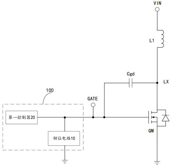
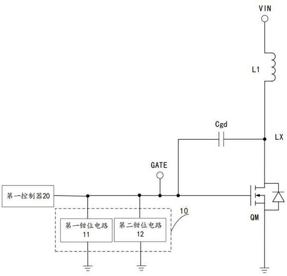
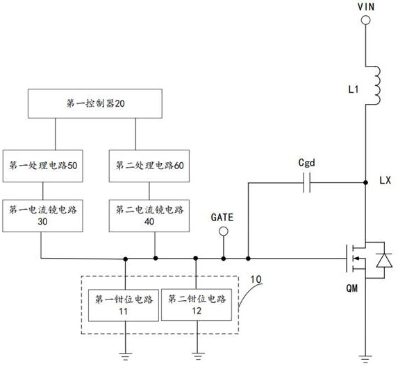
The invention relates to the field of voltage detection, and discloses a drain-source voltage detection circuit and a drain-source voltage detection method. The detection circuit comprises a clamping circuit and a first controller. The clamping circuit is electrically connected with a gate electrode of a main switch tube, and the first controller is electrically connected with the clamping circuit. When the main switch tube is turned off, the clamping circuit limits the gate voltage of the main switch tube within a positive clamping voltage or a negative clamping voltage, wherein the positive clamping voltage is smaller than the conduction threshold voltage of the main switch tube. Therefore, the drain-source voltage of the main switch tube is directly coupled to the clamping circuit through a gate-drain capacitor to form a first coupling signal, and the first controller detects the drain voltage of the main switch tube according to the first coupling signal. The detection circuit does not need to be additionally provided with an external assembly for sensing the drain voltage, so that noise coupling can be reduced, the detection accuracy is improved, the circuit structure is simplified, and the circuit cost is reduced.

Description

technical field [0001] The invention relates to the field of voltage detection, in particular to a drain-source voltage detection circuit and a drain-source voltage detection method. Background technique [0002] In various converters, soft switching technology is generally used to control the turn-on and turn-off of the main switch, that is, it is necessary to detect when the inductor current becomes zero, so that another energy transmission cycle can start, and the inductor and the main switch drain The capacitors on the electrodes form a resonance together, and it is necessary to detect the bottom of the resonance, so as to control the conduction of the main switch when the drain voltage reaches the bottom of the resonance waveform, so as to maximize the efficiency. [0003] Generally, a drain-source voltage detection circuit is used to detect when the inductor current and the drain voltage reach the bottom of the resonance valley, but in the current traditional drain-sou...

Claims


Application Information

Patent Timeline
IPC IPC(8): G01R19/00
CPCG01R19/0084
Inventor 蜜林德·古普塔
Owner HALO MICROELECTRONICS CO LTD
Learn More