
Drug stent and balloon spraying equipment

A technology of spraying equipment and balloons, which is applied to stents, spraying devices, balloon-shaped catheters, etc., can solve the problems of inability to guarantee the quality of spraying, high requirements for spraying environment, destruction of spraying and spraying environment, etc. Stable, avoid drug waste, ensure the effect of spraying quality

Pending Publication Date: 2022-03-01
LIAONING YINYI BIOTECH CO LTD
View PDF1 Cites 0 Cited by
  • Summary
  • Abstract
  • Description
  • Claims
  • Application Information

AI Technical Summary

Problems solved by technology

However, with this kind of equipment, it is impossible to continuously spray multiple workpieces without interruption, and the production efficiency is not high
Stop the work of the nozzle, remove the processed workpiece, and clamp the new workpiece, because the state of the ultrasonic nozzle when it is just started is different from the state when the nozzle is working smoothly, the quality of spraying when the nozzle is just restarted cannot be guaranteed
If the nozzle does not stop when the workpiece is replaced, or waits for the nozzle to work smoothly before spraying, it will cause waste of medicine
Moreover, when spraying, the requirements for the spraying environment are relatively high. Since the clamping area is located inside the spraying room, the spraying room will be connected to the external environment for a long time when clamping and disassembling the workpiece, which may damage the spraying area required for spraying. Pharmaceutical environment

Method used


Image

  • Drug stent and balloon spraying equipment
  • Drug stent and balloon spraying equipment
  • Drug stent and balloon spraying equipment

Examples


Embodiment 1

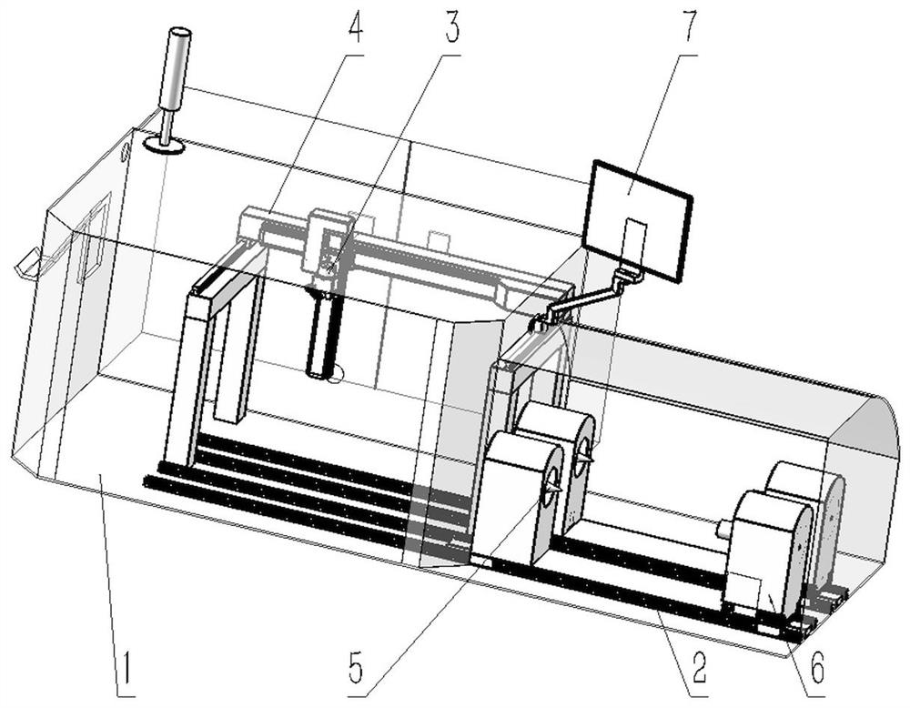
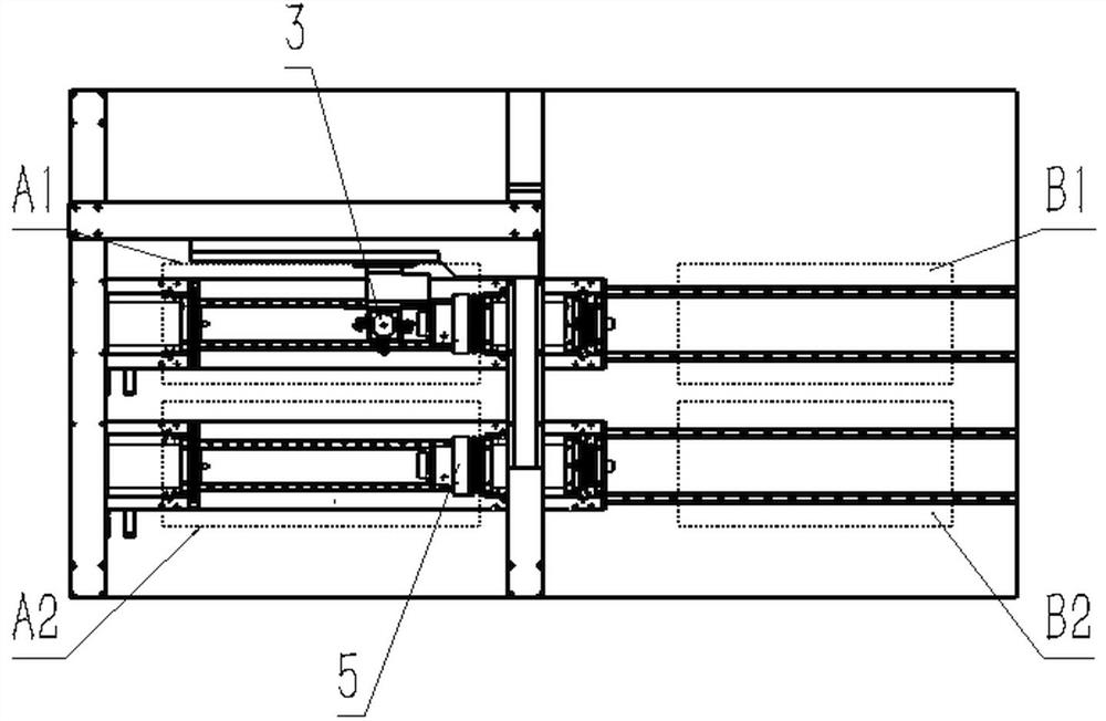
[0034] Such as figure 1 and figure 2 As shown, the overall structure of a drug stent and balloon spraying equipment includes a spraying chamber 1 , an ultrasonic nozzle 3 , a nozzle moving unit 4 , a clamping area 2 , a clamp 5 , and a clamp moving unit 6 .

[0035] The spray booth 1 is isolated from the external environment, and there are multiple processing positions in the spray booth 1 . In the case of this embodiment, there are processing position A1 and processing position A2. The shell of the spray booth 1 is made of light and thin aluminum material for surface anodic oxidation treatment, which is milky white, and other common metal or non-metal shells can also be used.

[0036] The clamping area 2 is arranged in the adjacent outer area of ​​the spray booth 1 and has a clamping position. There may be one clamping position, or there may be a plurality of clamping positions. In the case of this embodiment, there are clamping position B1 and clamping position B2.

[0...

Embodiment 2

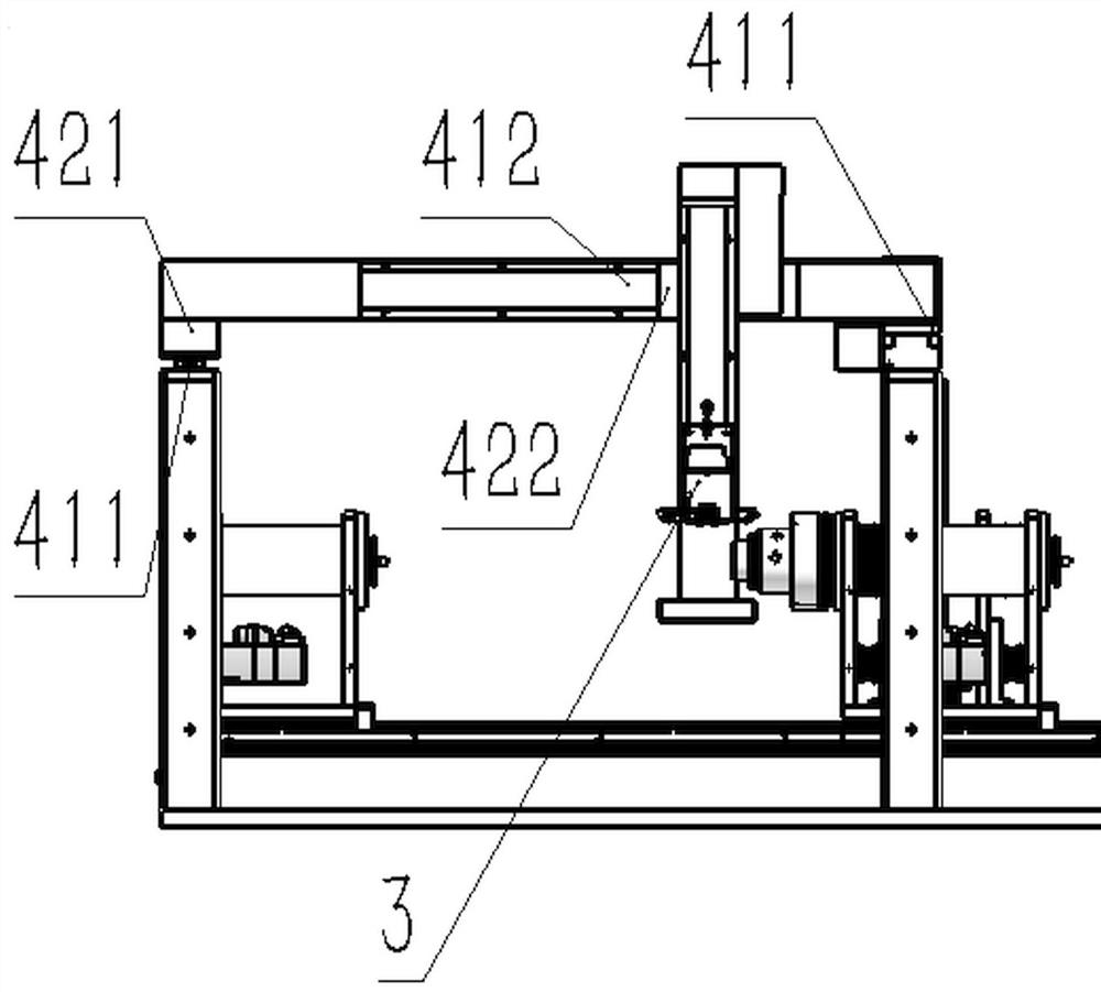
[0041] Such as image 3 As shown, the nozzle moving unit 4 includes two first guide rails 411, which are radially arranged in the spraying chamber 1 relative to the workpiece, and the two first guide rails 411 are parallel to each other; The workpiece moves radially; the second guide rail 412 is fixedly connected with the first slider 421 ; the ultrasonic nozzle 3 is fixedly connected with the second slider 422 and can move axially along the second guide rail 412 . In this embodiment, two first guide rails 411 parallel to each other are provided to improve the precision of movement, thereby improving the precision of drug application process and product quality, and only one first guide rail 411 may be provided.

[0042] The first sliding block 421 can slide on the first guide rail 411 to move the ultrasonic nozzle 3 between the processing position A1 and the processing position A2, thereby completing the station switching movement.

[0043]The second slider 422 can slide on ...

Embodiment 3

[0045] Such as Figure 4 As shown, in this embodiment, since the workpiece turning mechanism 63 is provided on the fixture moving unit 6 , the workpiece can be rotated in the circumferential direction, and the ultrasonic nozzle 3 does not need to move toward the workpiece and rotate around the workpiece axis. Corresponding mechanisms are therefore omitted in the nozzle displacement unit 4 . If the workpiece turning mechanism 63 is not provided on the fixture moving unit 6 , it is enough to design and add a mechanism in the nozzle moving unit 4 that can make the ultrasonic nozzle 3 move toward the workpiece and rotate around the workpiece.

[0046] Above, the nozzle moving unit of one embodiment constituted by guide rails and sliders has been described, but the nozzle moving unit can also be formed in other ways, for example, other embodiments such as threaded rods, rotating mechanisms, and mechanical arms can be used, as long as It only needs to enable the ultrasonic nozzle t...


PUM


Abstract

The invention relates to medicine stent and balloon spraying equipment which comprises a spraying chamber and a clamping area, an ultrasonic nozzle and a nozzle moving unit are arranged in the spraying chamber, and the ultrasonic nozzle is arranged on the nozzle moving unit and moves in the spraying chamber in the radial direction and the axial direction relative to a workpiece; the clamping area comprises a clamp and a clamp moving unit, and the clamp is arranged on the clamp moving unit and axially moves relative to the workpiece in the spraying chamber and the clamping area. The environment parameters in the spraying chamber are detected in real time, it can be guaranteed that the machining environment of spraying operation is stable, opening and closing of an opening are controlled through the clamp moving unit, a door opening and closing mechanism can be omitted, the structure is simple, manufacturing is convenient, and cost is saved; and the step of opening and closing a door can be omitted when the clamp and the workpieces move, meanwhile, the ultrasonic nozzle continuously sprays a plurality of workpieces through movement of the nozzle moving unit and the clamp moving unit and conversion of different stations, the production efficiency is improved, the spraying quality is guaranteed, medicine waste is avoided, and the medicine spraying environment cannot be damaged.

Description

technical field [0001] The invention relates to coating spraying equipment for medical instruments, in particular to a medicine bracket and balloon spraying equipment. Background technique [0002] In recent years, interventional or implantable medical devices with drug coatings have been widely used in the treatment of vascular restenosis. For example, drug balloons and drug-eluting stents, the surface of the device is uniformly coated with a polymer, and a layer of therapeutic drug coating is added on the polymer coating, and the drug-coated balloon or stent enters After entering the blood vessel, the drug is released gradually and slowly, so as to achieve the purpose of treating and preventing restenosis in the blood vessel. [0003] Currently, dipping, microinjection, and spraying are the more common methods for manufacturing such drug-coated medical devices. Among them, the spraying method is considered to be the most effective method for the preparation of drug coati...

Claims


Application Information

Patent Timeline
Patent Type & Authority Applications(China)
IPC IPC(8): B05B13/04B05B15/00A61M25/10A61F2/82
CPCB05B13/0442B05B15/00A61M25/1029A61F2/82A61M2025/1031
Inventor 董何彦王为张志新李红
Owner LIAONING YINYI BIOTECH CO LTD
Learn More