
Circumferentially-biased high-speed centrifugal impeller for inhibiting separation of boundary layer

A technology of boundary layer separation and high-speed centrifugation, which is applied to components of pumping devices for elastic fluids, liquid fuel engines, machines/engines, etc. Instability, low aerodynamic efficiency and other problems, to achieve the effect of improving the internal flow of the impeller and the uniformity of the outlet flow field, reducing the turbulent dissipation intensity, and not difficult to process

Active Publication Date: 2022-03-01
BEIHANG UNIV
View PDF12 Cites 1 Cited by
  • Summary
  • Abstract
  • Description
  • Claims
  • Application Information

AI Technical Summary

Problems solved by technology

However, the aerodynamic efficiency of high-speed centrifugal impellers is not high, the internal flow between the impellers is not stable, there are phenomena such as boundary layer separation, dynamic stall, etc., and surges are caused by flow changes, so the aerodynamic shape of the centrifugal impeller blades The design of the impeller and the structure of the flow channel are crucial to the flow efficiency and stability of the gas, and the structural strength and safety of the impeller under high-speed operation need to be tested

Method used


Image

  • Circumferentially-biased high-speed centrifugal impeller for inhibiting separation of boundary layer
  • Circumferentially-biased high-speed centrifugal impeller for inhibiting separation of boundary layer
  • Circumferentially-biased high-speed centrifugal impeller for inhibiting separation of boundary layer

Examples


Embodiment Construction

[0027] The following will clearly and completely describe the technical solutions in the embodiments of the present invention with reference to the accompanying drawings in the embodiments of the present invention. Obviously, the described embodiments are only some of the embodiments of the present invention, not all of them. Based on the embodiments of the present invention, all other embodiments obtained by persons of ordinary skill in the art without making creative efforts belong to the protection scope of the present invention.

[0028] In order to make the above objects, features and advantages of the present invention more comprehensible, the present invention will be further described in detail below in conjunction with the accompanying drawings and specific embodiments.

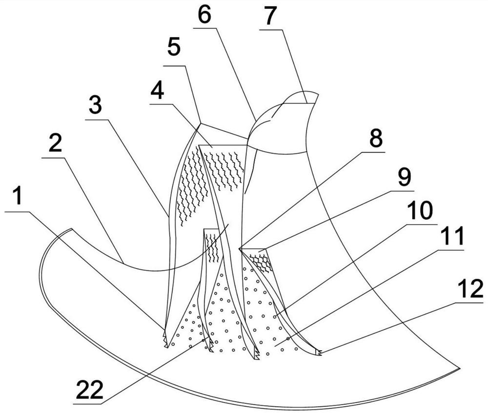
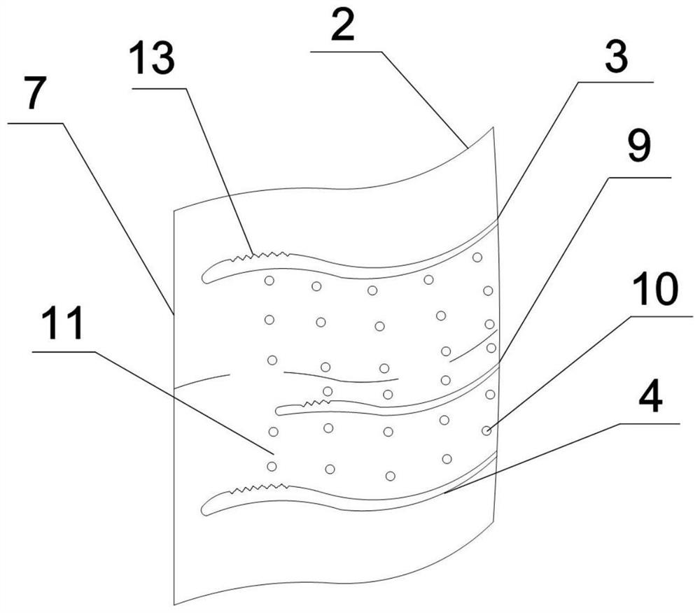
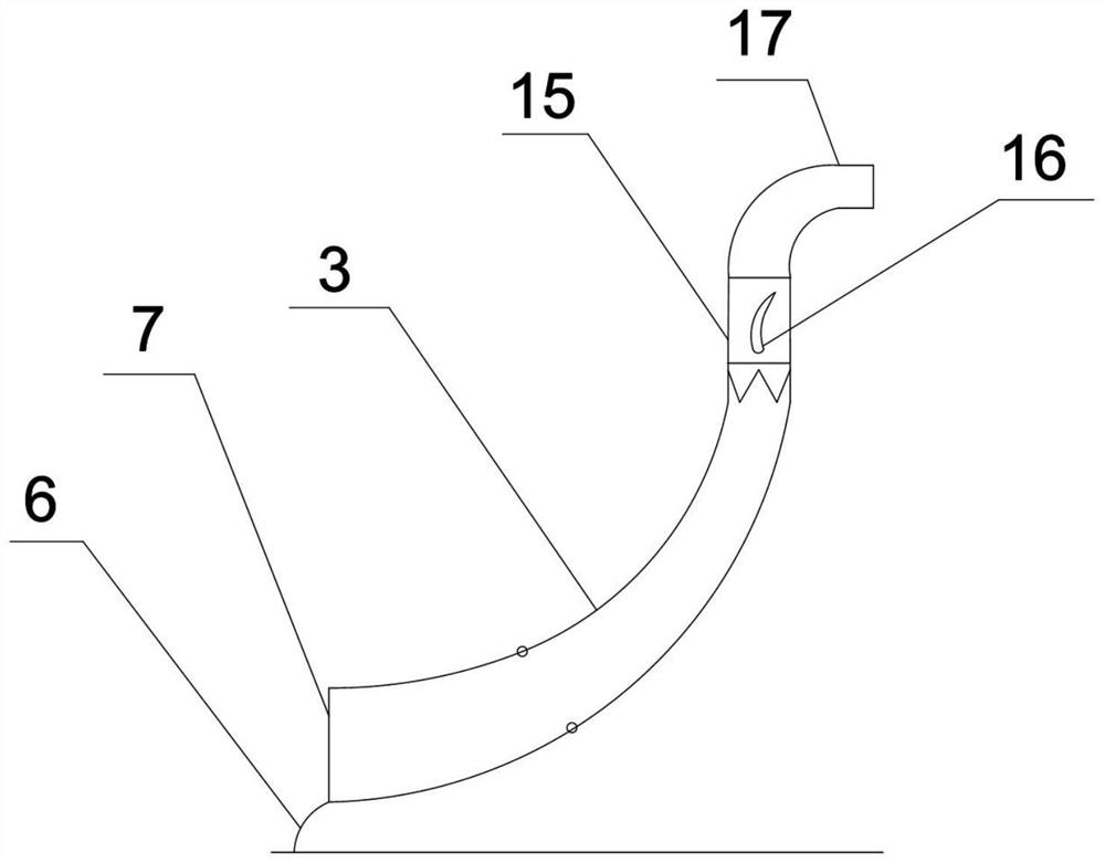
[0029] refer to Figure 1-7 , the present invention provides a circumferentially offset high-speed centrifugal impeller that suppresses the separation of the boundary layer, including a hub 2, the wa...


PUM


Abstract

The circumferential offset high-speed centrifugal impeller capable of restraining boundary layer separation comprises a hub, a blade set is fixedly connected to the wall face of the hub, a groove structure is arranged at the front end of the blade set, and a sawtooth tail edge is arranged at the tail end of the blade set; an inlet of the blade group is arranged close to an inlet of the impeller, and a blade runner is arranged on the blade group and is arranged on the wall surface of the hub; a flow guide cover hood is arranged at the inlet position of the blade group; the hub face is provided with a flow stabilizing plane used for restraining accumulation of low-energy airflow on the suction face. When the high-speed centrifugal impeller operates, the adhesion capacity of the surfaces of the blades to airflow can be improved, the turbulence dissipation strength of the wall faces of the wing-shaped blades can be weakened, and the acting capacity of the impeller to gas can be improved; the invention has the advantages of simple structure, low processing difficulty and finer structure, and is particularly suitable for civil small and medium-sized aero-engines / gas turbine compressors and load ends of small and special motors for acting to compress working media.

Description

technical field [0001] The invention relates to the technical field of internal combustion engines and gas turbines, in particular to a circumferentially offset high-speed centrifugal impeller that suppresses boundary layer separation. Background technique [0002] As a high-speed fluid machine, the centrifugal impeller is the core power component of the small and medium-sized aeroengine / gas turbine compressor. It can convert the kinetic energy of the fluid into the work done by the impeller, and compress the gas working medium to achieve deceleration and boosting. However, the aerodynamic efficiency of high-speed centrifugal impellers is not high, the internal flow between the impellers is not stable, there are phenomena such as boundary layer separation, dynamic stall, etc., and surges are caused by flow changes, so the aerodynamic shape of the centrifugal impeller blades The design of the impeller and the structure of the flow channel are crucial to the flow efficiency an...

Claims


Application Information

Patent Timeline
IPC IPC(8): F04D29/28F04D29/30F04D29/66
CPCF04D29/284F04D29/30F04D29/666F04D29/663F04D29/667Y02T10/12
Inventor 刘刚田康琪王坤董宝田乐韵郑世强
Owner BEIHANG UNIV
Learn More