Device and method for converting organic sulfur in blast furnace gas and method for regenerating organic sulfur conversion catalyst

A technology of a reforming device and blast furnace gas, which is applied in the field of blast furnace gas desulfurization, can solve the problems of high labor transportation cost, large pressure drop value, fast catalyst deactivation, etc. Effect

Active Publication Date: 2022-03-04
CHINA PETROLEUM & CHEM CORP +1
View PDF13 Cites 1 Cited by
  • Summary
  • Abstract
  • Description
  • Claims
  • Application Information

AI Technical Summary

Problems solved by technology

[0010] The purpose of the present invention is to overcome the large pressure drop value of the blast furnace gas organic sulfur conversion reactor in the prior art, the catalyst deactivation is fast, the device operation period is short, the deactivation For problems such as complex catalyst replacement operations and high manual transportation costs, a blast furnace gas organic sulfur conversion device, a blast furnace gas organic sulfur conversion method, and an organic sulfur conversion catalyst regeneration method are provided. The device can significantly reduce blast furnace gas passing through the catalyst bed. reduce the pressure drop of the layer, improve the conversion efficiency and life of the organic sulfur conversion catalyst, and at the same time realize the in-situ regeneration of the organic sulfur conversion catalyst, thereby ensuring the long-term stable operation of the blast furnace gas reformer

Method used


Image

  • Device and method for converting organic sulfur in blast furnace gas and method for regenerating organic sulfur conversion catalyst
  • Device and method for converting organic sulfur in blast furnace gas and method for regenerating organic sulfur conversion catalyst
  • Device and method for converting organic sulfur in blast furnace gas and method for regenerating organic sulfur conversion catalyst

Examples


Embodiment approach

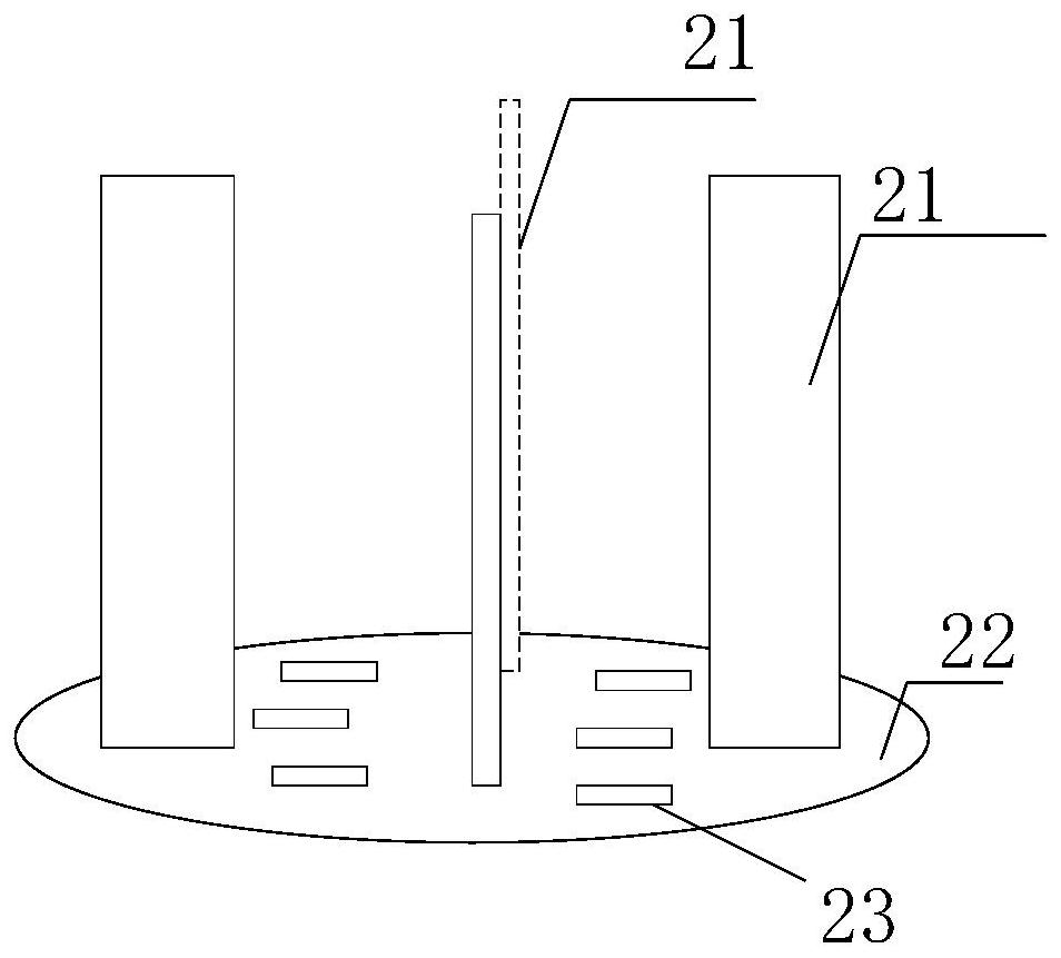
[0060] A preferred embodiment, one end of the rib in the gas distributor is a fixed connection, such as welding, and the other end and the gas inlet connection of the reactor are also fixed, such as welding.

[0061] Another preferred embodiment, the connection of one end of the rib in the gas distributor is a fixed connection, such as welding; the connection of the other end of the rib and the gas inlet of the reactor is removable, For example, hook. This connection method is used, which is more convenient for the loading and unloading of the catalyst.

[0062] According to the present invention, preferably, the diameter ratio of the disc in the diameter of the reactor is from 1 to 5: 1, preferably from 1 to 3: 1. Preferred conditions are used, more advantageous to uniformly distribute the blast furnace gas in the surface of the catalyst bed, and improve the catalyst efficiency of the catalyst.

[0063] Preferably, a hole is provided on the disc; further preferably, the opening r...

Embodiment 1

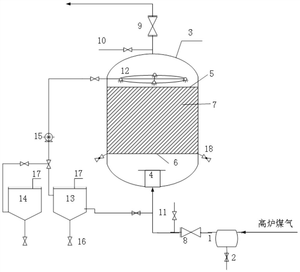
[0144] (1) Blast furnace gas organic sulfur conversion device, such as figure 1 As shown, the conversion device includes: a liquid distribution package 1, a guide valve 2, a reactor 3, a spray regeneration system, a reactor 3 (downward) including a gas distributor 4, an upper grid assembly 5, a lower layer Grid assembly 6, an organic sulfur conversion catalyst bed 7, an inlet shutoff valve 8, an outlet shutoff valve 9, a purge line inlet 10, a purge line outlet 11, a catalyst discharge port 18.

[0145]The spray regeneration system includes a regenerative liquid storage tank 14 mounted outside the reactor 3, a cleaning liquid storage tank 13, a pump 15, a delivery line, a tap water line 17, a bottom valve 16, and an interior mounted to reactor 3. The spray regeneration line 12 and the nozzle 27 disposed on the spray regeneration line 12, wherein the spray regeneration line 12 is each in line with the regenerative liquid storage tank 14 and the cleaning liquid storage tank 13, and ...

Embodiment 2

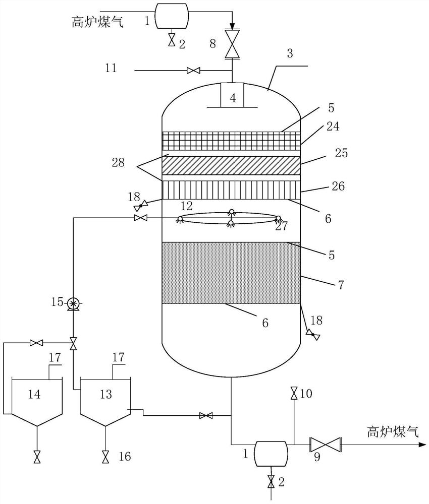
[0158] (1) Blast furnace gas organic sulfur conversion device, such as image 3 As shown, the conversion device includes: a collector package 1, a guide valve 2, a reactor 3, a spray regeneration system; reactor 3 (uploading) includes a gas distributor 4, an upper grid assembly 5, a lower layer? The gate assembly 6, the inlet shutoff valve 8, the outlet shutoff valve 9, the purge line inlet 10, the purge line outlet 11, the catalyst discharge opening 18, the dust filter bed 24, the degrading bed 25, the deoxidizer bed 26 , Organic sulfur conversion catalyst bed 7, alumina porcelain ball 28, reactor adopted as follows. The spray regeneration system includes a spray regeneration line 12, four nozzles 27, a cleaning liquid storage tank 13, a regenerative liquid storage tank 14, a pump 15, a bottom valve 16, and a tap water line 17.

[0159] The spray regeneration system includes a regenerative liquid storage tank 14 mounted outside the reactor 3, a cleaning liquid storage tank 13, a p...


PUM

PropertyMeasurementUnit
diameteraaaaaaaaaa
porosityaaaaaaaaaa
porosityaaaaaaaaaa

Abstract

The invention relates to the technical field of blast furnace gas desulfurization, in particular to a blast furnace gas organic sulfur conversion device and method and an organic sulfur conversion catalyst regeneration method. The conversion device comprises a reactor containing a gas distributor and at least one catalyst bed layer, a spraying regeneration system and at least one liquid collection bag, the catalyst bed layer comprises an organic sulfur conversion catalyst bed layer, the spraying regeneration system is used for cleaning and/or regenerating the catalyst bed layer, and the liquid collection bag is used for collecting the organic sulfur conversion catalyst bed layer. The liquid collecting bag is used for collecting water in the blast furnace gas and optional liquid for cleaning and/or regenerating the catalyst bed layer; wherein the ratio of the height of the catalyst bed layer to the diameter of the reactor is (0.1-2): 1. The conversion device provided by the invention can significantly reduce the pressure drop of blast furnace gas passing through the catalyst bed layer, improve the conversion efficiency of organic sulfur, and realize in-situ regeneration of the organic sulfur conversion catalyst, thereby ensuring long-term stable operation of the blast furnace gas conversion device.

Description

Technical field [0001] The present invention relates to the field of blast furnace gas desulfurization techniques, and more particularly to a blast furnace gas organic sulfur conversion device, a blast furnace gas organic sulfur conversion method and an organic sulfur conversion catalyst regeneration method. Background technique [0002] In the prior art, the blast furnace gas is generally delivered to the power plant boiler, the refining plant hot air furnace, steel mills, etc., which are used as fuel, and the production is large and widely used. At present, the blast furnace gas is not directly used as a fuel use of other devices in the plant, which can cause SO in flue gas emissions of each device. 2 The content exceeds the national ultra-net emission requirements, and the environmental protection pressure of each steel plant is huge. [0003] Since sulfur in blast furnace gas is mainly organic sulfur, hydrogen sulfide only occupies less, h 2 S can be removed by alkaline washi...

Claims


Application Information

Patent Timeline
Patent Type & Authority Applications(China)
IPC IPC(8): B01D53/86B01D53/48C10K1/00C10K1/34B01J8/02B01J38/64B01J38/48
CPCB01D53/8603C10K1/004C10K1/34B01J8/025B01J8/0278B01J38/64B01J38/48B01J2208/00911Y02P20/584
Inventor 张翊于宁何金龙张同旺
Owner CHINA PETROLEUM & CHEM CORP
Why Eureka
Try Eureka