Acrylate foaming reflector plate, preparation method thereof and backlight module

A technology of acrylate and reflective sheet, which is applied in the direction of optics, optical components, coatings, etc., and can solve problems such as insufficient stiffness

Pending Publication Date: 2022-03-04
DONGGUAN GUANGZHI PHOTOELECTRIC CO LTD
View PDF0 Cites 0 Cited by
  • Summary
  • Abstract
  • Description
  • Claims
  • Application Information

AI Technical Summary

Problems solved by technology

[0005] However, the current reflective sheet made of polyester resin often needs to be stretched and oriented during the

Method used


Image

  • Acrylate foaming reflector plate, preparation method thereof and backlight module
  • Acrylate foaming reflector plate, preparation method thereof and backlight module
  • Acrylate foaming reflector plate, preparation method thereof and backlight module

Examples


preparation example Construction

[0044] The present invention also provides a method for preparing an acrylate foam reflective sheet, comprising the following steps:

[0045] A) immersing the porous nanoparticles in a foaming solvent and stirring to obtain porous nanoparticles adsorbed with a foaming solvent;

[0046] Described foaming solvent is one or more in normal heptane and normal hexane;

[0047]B) mixing porous nanoparticles adsorbed with a foaming solvent and UV acrylate resin, coating the surface of the PET substrate, and curing to obtain a foaming layer;

[0048] C) Compounding a protective layer on the surface of the foam layer to obtain an acrylate foam reflective sheet.

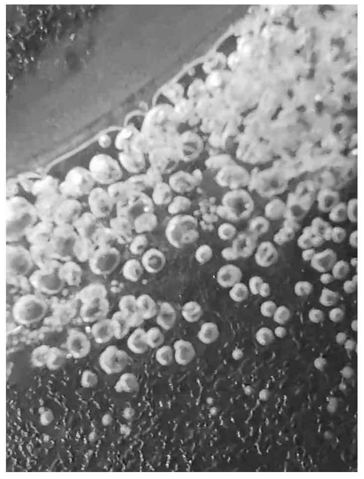
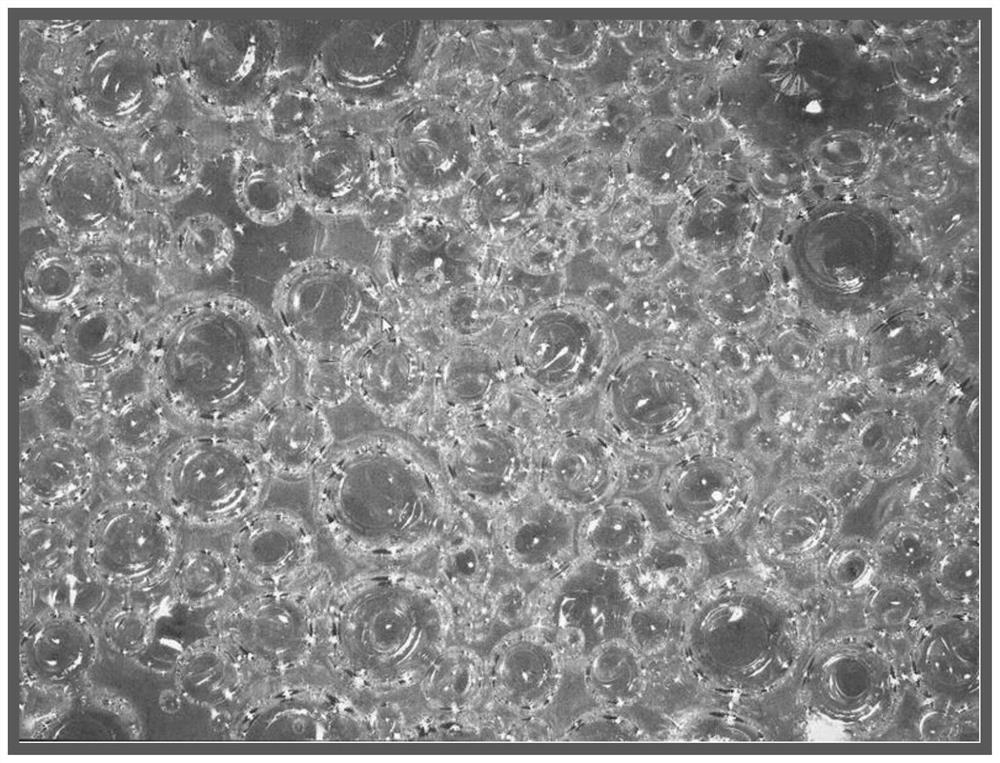
[0049] In the present invention, the porous nanoparticles are immersed in the foaming solvent, and the foaming solvent is stirred to fill the pore structure inside of the porous material. In order to avoid the premature volatilization of the adsorbed foaming solvent, the porous nanoparticles adsorbed with the foaming solvent s...

Embodiment 1

[0070] 20g particle size is 20nm, specific surface area is 385m 2 / g SiO 2 , soaked in 50mL of acetone, at room temperature or 20°C, using centrifugal rotation 1800rpm / 10min to speed up the mixing, the mixed SiO 2 Take it out and store it in an environment below 20°C for later use.

[0071] Take 5g of the above mixed SiO 2 , at room temperature or below 20°C, uniformly stirred and dispersed in 50 g of ultraviolet light acrylic resin with a refractive index of 1.562 to obtain a coating liquid.

[0072] Take the 100 μm PET base film, and apply the above coating solution to the surface of the PET base film, the coating machine speed is 10m / m, and the thickness of the coating layer is controlled to 30 μm;

[0073] The curing process is as follows:

[0074] The energy of the first light source is 20mW / cm2 for pre-curing, the light curing wavelength is LED 365nm light source, and the machine speed is 10m / min, so that the porous SiO2 in the UV glue 2 The acetone in the UV glue p...

Embodiment 2~3

[0079] A white reflective sheet was prepared according to the method in Example 1, except that in Examples 2 and 3, acrylic resins with a refractive index of 1.583 and 1.602 were used instead of the acrylic resin with a refractive index of 1.562 in Example 1.


PUM

PropertyMeasurementUnit
Particle sizeaaaaaaaaaa
Specific surface areaaaaaaaaaaa
Viscosityaaaaaaaaaa

Abstract

The invention provides an acrylate foaming reflector plate. The acrylate foaming reflector plate comprises a PET base material, a foaming layer and a protective layer which are in contact in sequence, the foaming layer is acrylate resin in which porous nanoparticles and bubbles are dispersed; the porous nanoparticles are dispersed in gaps of the bubbles; the particle size of the porous nanoparticles is 10-50nm, and the specific surface area of the porous nanoparticles is 300-500m < 2 >/g. According to the invention, acrylate resin capable of being photo-cured is used as a foaming layer, a seedless foaming process is adopted for foaming, and foaming points of the finally obtained white reflector plate are positioned near the porous nanoparticles. As the size of the bubbles can be controlled at the nanometer level, compared with a PET polyester foaming layer formed through stretching in the prior art, the PET polyester foaming layer can achieve thinner thickness and has more excellent stiffness. The invention further provides a preparation method of the acrylate foaming reflector plate and a backlight module.

Description

technical field [0001] The invention belongs to the technical field of liquid crystal display, and in particular relates to an acrylate foam reflection sheet, a preparation method thereof and a backlight module. Background technique [0002] The backlight module is a backlight component in LCD display products. It is generally composed of a backlight source, a multi-layer backlight material and a supporting frame. The quality of the backlight determines important parameters such as the brightness of the LCD display, the uniformity of the emitted light, and the color scale. To a large extent, it determines the luminous effect of the LCD screen. [0003] The backlight module includes a lighting source, a reflector, a light guide plate, a diffuser, a brightness enhancement film (prism sheet), and a frame. The function of the reflector is to reflect the light that is not facing the light-emitting surface, so as to prevent the illumination light from escaping to the back of the ...

Claims


Application Information

Patent Timeline
IPC IPC(8): G02B5/08B05D7/24B05D7/02B05D3/06B05D3/02
CPCG02B5/0841B05D7/02B05D7/24B05D3/067B05D3/0263B05D2502/00B05D2601/20B05D2201/02
Inventor 邓建东陈明源
Owner DONGGUAN GUANGZHI PHOTOELECTRIC CO LTD
Why Eureka
Try Eureka