
Directional heat transfer pavement applied to ice and snow melting of airport and control method of directional heat transfer pavement

A control method, ice and snow technology, applied to the condensing pavement paved on site, roads, roads, etc., can solve the problems of unintelligent control mode of asphalt pavement of heating cables, damage of heating cables, low transmission efficiency, etc., and achieve pavement cost High, prolong service life, improve the effect of structural strength

Active Publication Date: 2022-03-08
SOUTHWEST JIAOTONG UNIV
View PDF5 Cites 0 Cited by
  • Summary
  • Abstract
  • Description
  • Claims
  • Application Information

AI Technical Summary

Problems solved by technology

However, in the process of melting ice and snow, the traditional electric heating pavement will have the problems of scattered energy, low transmission efficiency and unintelligent regulation of the heating cable on the asphalt pavement, which will cause serious damage to the heating cable.
The present invention solves the problem of scattered energy and low transmission efficiency on electric heating pavements by providing a directional heat transfer pavement and its control method applied to melting ice and snow in airports. At the same time, the use of heating cables is improved by changing the control mode. Life expectancy, reducing pavement renovation and maintenance

Method used


Image

  • Directional heat transfer pavement applied to ice and snow melting of airport and control method of directional heat transfer pavement
  • Directional heat transfer pavement applied to ice and snow melting of airport and control method of directional heat transfer pavement
  • Directional heat transfer pavement applied to ice and snow melting of airport and control method of directional heat transfer pavement

Examples


Embodiment Construction

[0037] The specific embodiments of the present invention are described below so that those skilled in the art can understand the present invention, but it should be clear that the present invention is not limited to the scope of the specific embodiments. For those of ordinary skill in the art, as long as various changes Within the spirit and scope of the present invention defined and determined by the appended claims, these changes are obvious, and all inventions and creations using the concept of the present invention are included in the protection list.

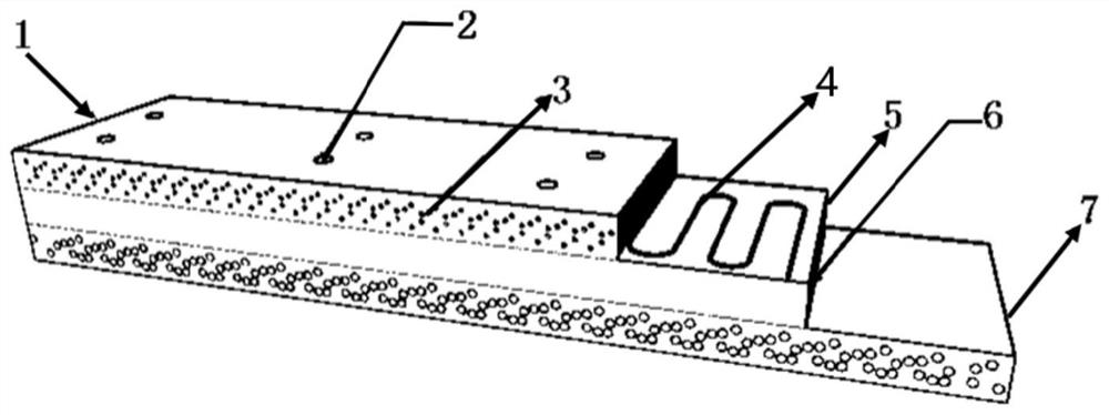
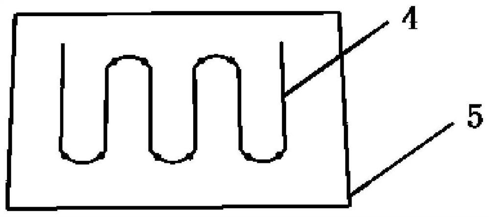
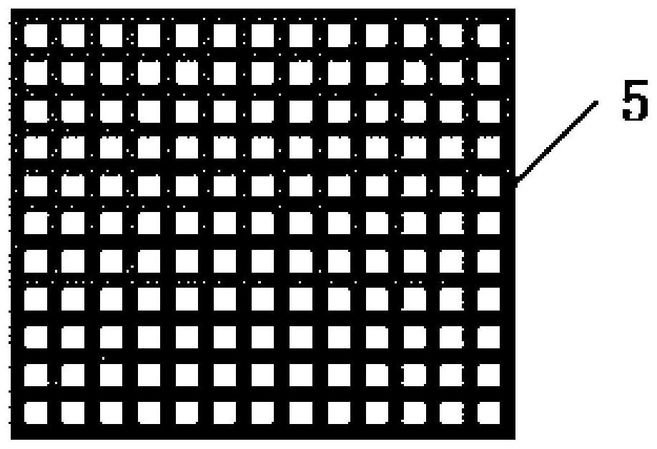
[0038] A directional heat transfer pavement and its control method applied to melting ice and snow in airports, such as figure 1 As shown, its structure includes gravel base, ordinary asphalt concrete lower layer, heat insulation layer, heating cable, and heat-conducting concrete upper layer from bottom to top. The base is a large-size crushed stone base. The traditional semi-rigid base has a weak bearing capacity and is pr...


PUM

PropertyMeasurementUnit
Thicknessaaaaaaaaaa
Thicknessaaaaaaaaaa
Thicknessaaaaaaaaaa

Abstract

The invention discloses a directional heat transfer pavement applied to ice and snow melting of an airport and a control method thereof, the directional heat transfer pavement comprises a structure and a control method, and the structure comprises a macadam base layer, a common asphalt concrete lower surface layer, a heat insulation layer, a heating cable and a heat conduction concrete upper surface layer from bottom to top. The heat insulation layer is used for preventing heat from being transferred downwards and ensuring that the heat is gathered on the upper surface layer; the heat-conducting concrete upper surface layer is formed by mixing iron particles or other heat-conducting media into asphalt concrete according to a certain proportion and the heat-conducting performance of the heat-conducting concrete upper surface layer. According to the structure, the heat transfer theory is utilized, when the upper surface temperature reaches the ice and snow melting requirement, the voltage smaller than the rated power is controlled, and the heating cable is continuously heated. According to the directional heat conduction structure provided by the invention, the problems of heat dissipation and low heat transfer efficiency of a traditional electric heating road surface are solved, and the continuous heating control method of the directional heat conduction structure solves the problems of short service life and invariable replacement caused by repeated electrification of a heating cable during intermittent heating.

Description

technical field [0001] The invention relates to an intelligent ice and snow melting road surface, in particular to a directional heat transfer road surface applied to airport ice and snow melting and a control method thereof. Background technique [0002] Snow and icing on airport runways in winter have caused many safety hazards for aircraft take-off and landing, and have seriously affected people's own safety. In ice and snow weather, road adhesion is greatly reduced, which is quite unfavorable to the dynamics and safety of aircraft driving. The common method of ice and snow removal on the road surface now mainly includes manual or mechanical removal method, the snow melting effect is not good, and all carry out snow melting under the situation of icy and snowy road surface, can not prevent before freezing and snow accumulating. In the early 1990s, foreign electric heating technology was introduced into China, and heating cables were buried under the road surface, and the...

Claims


Application Information

Patent Timeline
IPC IPC(8): E01C7/32E01C11/26
CPCE01C7/32E01C11/265
Inventor 战友李泽仁朱安琪许书铭郭启骋卢立恒
Owner SOUTHWEST JIAOTONG UNIV
Learn More