Supercharge Your Innovation With Domain-Expert AI Agents!

Measuring device for optical fiber light darkening and use method

A measuring device and fiber laser technology, applied in measuring devices, photometry, optical radiation measurement, etc., can solve problems such as high price of high-power laser power meters, inaccurate laser power measurement, and unfavorable progress of scientific research projects, etc., to achieve Reduce power detection instability, increase stripping efficiency, and simple structure

Pending Publication Date: 2022-03-08
CHINA ELECTRONICS TECH GRP NO 46 RES INST
View PDF5 Cites 0 Cited by
  • Summary
  • Abstract
  • Description
  • Claims
  • Application Information

AI Technical Summary

Problems solved by technology

[0004] Most of the existing high-power laser power meters are thermal radiation power meters, and the power meters are cooled by air-cooled or water-cooled refrigeration methods. When measuring power, the output laser needs to be aligned with the center of the power meter probe to increase the power. However, when the power meter works for a long time, the output of the power meter will fluctuate due to changes in the ambient temperature and the cooling effect of the water cooler, resulting in inaccurate laser power measurement; high-power laser irradiation for a long time on the power meter probe will cause There are dead spots in the probe, which affects the measurement accuracy, and the high-power laser power meter is expensive, and frequent replacement of the probe increases the test cost, which is not conducive to the advancement of scientific research projects

Method used


Image

  • Measuring device for optical fiber light darkening and use method
  • Measuring device for optical fiber light darkening and use method
  • Measuring device for optical fiber light darkening and use method

Examples


Embodiment Construction

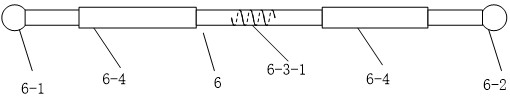
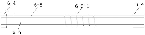
[0024] Such as figure 1 As shown, a measuring device for optical fiber photodarkening includes a high-power fiber laser 1 , a cooling device 2 , a laser receiver 3 and a photodetector 5 , and also includes a reflector 4 and a receiving optical fiber 6 .

[0025] The laser receiving body 3 is installed in the cooling device 2 , and the cooling device 2 cools the laser receiving body 3 .

[0026] The surface of the reflector 4 is coated with a reflective film of 1060-1100nm, and the back of the reflector 4 is provided with an angle adjustment device, which can adjust the angle between the reflective surface of the reflector 4 and the receiving surface of the laser receiver 3, and the reflected power can be realized by adjusting the angle. When the scattered laser light is incident on the surface of mirror 4 at 45° or 60°, it can be completely reflected, and the reflected laser power is 100%. When the incident light is incident at 50°, the reflected laser power is 85%, and so on...


PUM


Abstract

According to the measuring device for optical fiber light darkening and the using method, laser output by a high-power optical fiber laser is received by a laser receiver, the scattered laser is reflected to a receiving optical fiber through a reflector, and laser existing in a receiving optical fiber cladding is stripped through a cladding light filtering device; the photoelectric detector is used for sensing the intensity of the laser output from the fiber core; adjusting the power of the optical fiber laser to the maximum, adjusting the angle of the reflecting surface of the reflecting mirror to ensure that the light intensity sensed by the photoelectric detector is unsaturated, and recording the laser intensity sensed by the photoelectric detector when the power supply outputs different currents; replacing the laser receiving body with a high-power laser power meter, ensuring the same position of the high-power laser power meter and the laser receiving body, and recording corresponding laser power of the power supply at different output currents; and establishing a corresponding relation between the laser intensity sensed by the photoelectric detector and the laser power, and fitting the corresponding relation through a least square method. And long-time power monitoring of high-power laser can be realized.

Description

technical field [0001] The invention relates to the field of optical power measuring devices for fiber lasers, in particular to a measuring device for optical fiber photodarkening and a use method. Background technique [0002] In recent years, as the output power of ytterbium-doped fiber lasers continues to rise and the application fields continue to expand, the output power of common fiber lasers in the civilian market has grown from 1kw five years ago to 10kw now, and even 20kw fiber lasers have appeared. Therefore, higher requirements are put forward for the stability of its output power. However, the Yb-doped fiber is restricted by the photon darkening effect during long-term high-power operation, which reduces its output power and deteriorates its stability, which severely limits fiber lasers. further development. [0003] The photon darkening effect refers to the phenomenon that when the ytterbium-doped fiber works at high power and for a long time, the power drops, ...

Claims


Application Information

Patent Timeline
IPC IPC(8): G01J1/42G01J1/04
CPCG01J1/42G01J1/0411G01J1/0425Y02A90/10
Inventor 高培瑞杨鹏庞璐衣永青刘永健韩志辉张佳琦赵国骁
Owner CHINA ELECTRONICS TECH GRP NO 46 RES INST
Features
  • R&D
  • Intellectual Property
  • Life Sciences
  • Materials
  • Tech Scout
  • Unparalleled Data Quality
  • Higher Quality Content
  • 60% Fewer Hallucinations
Learn More