Seawater desalination device
A seawater and water tank technology, applied in circuit devices, seawater treatment, battery circuit devices, etc., can solve the problems of complex structure, high cost, and unsuitability for household use of seawater desalination devices, and achieve the effect of simple structure, low cost, and simple installation
- Summary
- Abstract
- Description
- Claims
- Application Information
AI Technical Summary
Problems solved by technology
Method used
Image

Examples
specific Embodiment approach 1
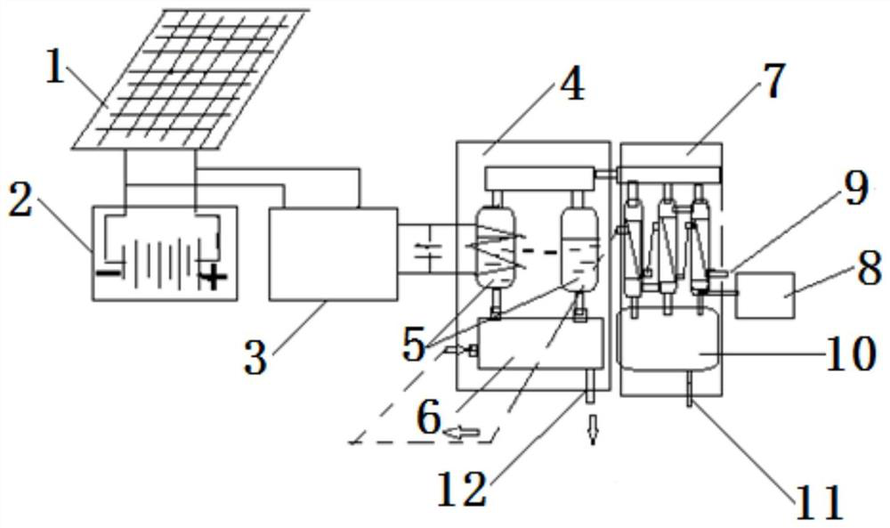
[0015] Specific implementation mode one: combine figure 1 Describe this embodiment, this embodiment includes a photovoltaic panel 1 and a battery pack 2, the battery pack 2 is electrically connected to the photovoltaic panel 1, it also includes a high-frequency induction heating module power supply 3, an induction heating steam generator 4, an induction Indirect heating heating module group 5, sea water tank 6, vacuum cooling device 7, vacuum pump fan 8, sea water inlet pipe 9, fresh water tank 10, fresh water outlet pipe 11 and salt water discharge pipe 12, induction indirect heating heating module group 5 installation On the induction heating steam generator 4, the sea water tank 6 is connected to the lower end of the induction heating steam generator 4, the battery pack 2 and the induction indirect heating heating module group 5 are connected through the high frequency induction heating module power supply 3, and the salt water The discharge pipe 12 is installed at the wate...
specific Embodiment approach 2
[0023] Specific implementation mode two: combination figure 1 To describe this embodiment, the photovoltaic panel 1 of this embodiment has an area of 1.5-2.8 square meters. With such a setting, it is convenient to choose a photovoltaic panel of a suitable size according to household or industrial use, and at the same time, it can also meet the power supply demand. Other compositions and connections are the same as in the first embodiment.
specific Embodiment approach 3
[0024] Specific implementation mode three: combination figure 1 The present embodiment will be described. The degree of vacuum of the induction heating steam generator 4 of the present embodiment is 100 mbar. Such arrangement is convenient for lowering the boiling point of seawater evaporation. Other compositions and connections are the same as those in Embodiment 1 or Embodiment 2.
[0025] Specific implementation mode four: combination figure 1 To describe this embodiment, the induction indirect heating heating module group 5 of this embodiment is made by winding multiple sets of copper coils. Such setting facilitates the expected heating effect. Other compositions and connections are the same as those in Embodiment 1, 2 or 3.
[0026] Specific implementation mode five: combination figure 1 The present embodiment will be described. The boiling point of seawater in the induction heating steam generator 4 of the present embodiment is 48-60 degrees Celsius. With such sett...
PUM
| Property | Measurement | Unit |
|---|---|---|
| Area | aaaaa | aaaaa |
Abstract
Description
Claims
Application Information
 - Generate Ideas
- Intellectual Property
- Life Sciences
- Materials
- Tech Scout
- Unparalleled Data Quality
- Higher Quality Content
- 60% Fewer Hallucinations
Browse by: Latest US Patents, China's latest patents, Technical Efficacy Thesaurus, Application Domain, Technology Topic, Popular Technical Reports.
© 2025 PatSnap. All rights reserved.Legal|Privacy policy|Modern Slavery Act Transparency Statement|Sitemap|About US| Contact US: help@patsnap.com